This article series analyses the geometrical representation of various signals when being cut/pressed onto a lacquer/vinyl record. It is meant to help understand the physical subtleties of the process.
Part four of the series looks into the representation of a sawtooth wave on a disk record.
Note how the original waveform shape (sawtooth) maps to a horizontal movement equivalent to the signal’s waveform. The width/depth of the groove remains equal throughout.
1 kHz Sawtooth, Panned Left
Panned left, only the inner groove wall shows relevant features. The outer groove wall remains almost flat, but not perfectly. This shows the relatively strong stereo cross-talk inherent to the format (compared to modern digital formats).
1 kHz Sawtooth, Panned Right
Panned right, only the outer groove walls show features, while the inner walls remain almost featureless. The presence of a strong stereo cross-talk is obvious.
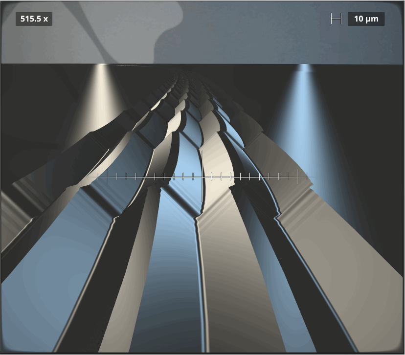
1 kHz Sawtooth, Antiphase
With a stereo sawtooth signal in negative correlation, only the vertical axis gets modulated, with the groove purely moving up and down. This can be seen by the straight center line and a modulating groove width. Note that groove width is always twice groove depth.