This article series analyses the geometrical representation of various signals when being cut/pressed onto a lacquer/vinyl record. It is meant to help understand the physical subtleties of the process.
Part two of the series looking into the representation of a clipped sine wave on a disk record.
Clipped waveforms produce challenging geometries for the mechanical devices involved in the process. The characteristic flanks appearing in the groove can provoke the pickup stylus to jump from flank to flank, grossly misstracking the underlying signal. Clipping also substantially increases the accelerations necessary to follow the groove, in turn also stressing the cutting stylus (i.e. its coils) quite a bit.
1 kHz Sine, Panned Left, Heavily Clipped
Panned left, the outer flank of the groove remains flat.
1 kHz Sine, Panned Right, Heavily Clipped
Panned right, the inner flank of the groove remains flat.
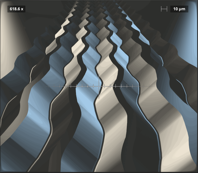
1 kHz Sine, Antiphase, Heavily Clipped
With one side polarity inverted, the modulation will purely affect groove width/depth, and maintain zero horizontal excursion. Similar to the pure sine wave example, the addition of clipping only makes the half-pipes more “exciting” for the pickup stylus. The abrupt changes in groove depth inspire the stylus to challenge gravity, in particular if the tonearm isn’t adjusted correctly.