The Concept
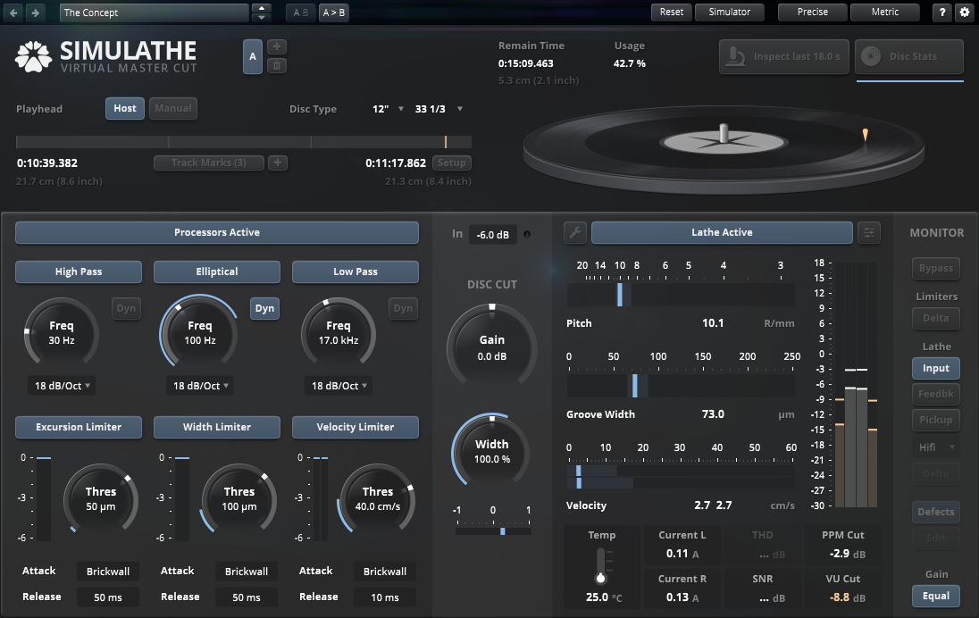
The SimuLathe product family is made to replicate the complete disk mastering process. It does so by using an accurate parametric model of a cutting lathe, in turn generating a precise 3 dimensional representation of the written disk groove. This groove can be analyzed in detail, with virtual pickups being able to track this groove and convert their geometry back into audio.
The modelling of the lathe is interesting in so far that it does not attempt to emulate a specific machine/setup. Instead, it took over what the forefathers of today’s most popular cutting lathes and their periphery intended to achieve. By focusing on building the most ideal, yet physically feasible cutting lathe, SimuLathe is able to flexibly parametrize the process and yield highly accurate results both in terms of geometry and audio fidelity (disc space consumption, audio losses). SimuLathe can also be adjusted to match any modern or vintage hardware with great accuracy.
The CUT edition is tailored to audiences who directly operate disk cutting systems. Its detailed calibration options permit for most real world cutting systems to be replicated within tight tolerances. The result is a separate cutting room, immune to wear and tear. This separate “cutting room” not only offers exciting potential in terms of quality control, audio mastering and authoring, it also represents and excellent reference for long term maintenance and calibration of the real cutting system itself.
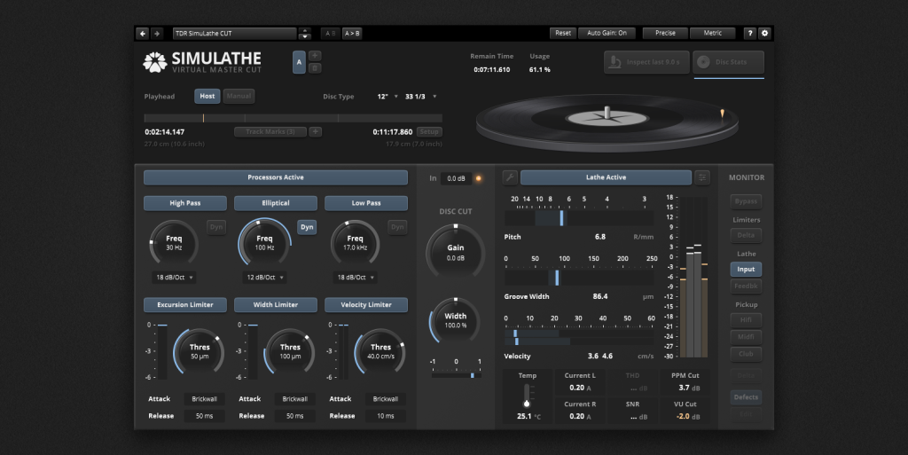
Inspired by the structure of real world cutting systems, SimuLathe is segmented into distinct modules:
- Project configuration (playhead setup and disk parameters).
- Audio preprocessors
- A representative virtual cutting lathe that can be calibrated to match closely any existing hardware.
- An extensive monitoring section
- Disc statistics inspection
- Groove microscope
The sandbox nature of SimuLathe suites a wide range of workflows. At one extreme, SimuLathe can be used passively prior to the actual cut, helping generate a safe, near optimal starting point. It helps locate the most critical hotspots in the material, from geometrical to audio issues, without ever touching a lacquer. Disc space consumption can be precisely estimated and optimized upfront, and the artist can be provided with cost effective digital test cuts.
At the other extreme, SimuLathe CUT offers a wide range of advanced metering and pre-processing abilities, from precise filters to unique geometrically aware limiters. With these, SimuLathe can be used to drive a cut directly.
Quickstart Guide
This section will show you how to get up and running with SimuLathe as quickly as possible.
Before you begin with SimuLathe:
- SimuLathe is a disc-mastering-studio like any other – levels need to be calibrated.
- Factory default level settings are -6dBFS <-> 7cm/s (1kHz sine). We recommend leaving it like this for a quick start. Later you can calibrate SimuLathe to the levels used in your cutting room. We provide a detailed to-do list for checking and calibration. Personal support is possible.
To set up and get started with SimuLathe:
- Create a new session or project in your DAW.
- Create an audio track.
- Import audio files into the audio track in your preferred order with a gap between tracks.
- Insert the SimuLathe CUT plugin on the audio track.
- Move the DAW playhead to the start of the first audio file then select the Set button for Side Start. Note: This step is not required if the first audio file starts at 00:00:000.
- Move the DAW playhead to the end of the last audio file then select the Set button for Side End.
- Select the Disc Time Confirmation (Ok) button to complete the disc time setup and close the setup panel.
- Select a factory preset to audition from the preset drop-down list.
- Start playback in your DAW.
To create Track Marker locations:
- Move the DAW playhead to the beginning of a track.
- Select the Add New Track Marker button. The marker is created and appears in the track marker menu.
- Repeat the above steps for each additional track.
Calibrating SimuLathe to a Real System
SimuLathe can be calibrated to your existing cutting system. Please use the following checklist as a starting point.
Basic settings in SimuLathe
- Set Velocity 0dB (1kHz lateral) in SL to the value of your test-record used to calibrate the drive level on your system. In most cases this will be 7cm/s, which serves as a suitable starting point. It’s important to note that the information provided on the record sleeve may not always represent the peak value for a 1kHz lateral sine wave. If you notice a significant offset between SimuLathe and your physical pitch system (as described later), feel free to adjust this value.
- Set Reference level (peak) in SL to the dBFS value that a 1kHz sine wave in your studio must leave your DAW in order to get the studio’s analog reference level (In most cases this will be 0VU/1.23V) for calibrating the drive level on your system.
- Set the minimal depth according to your system and calibration. For VMS66/70 and DJR this will be standard 50µm / 2mil), for FloKaSon this will be standard 55µm, for VMS80 this will be the same as the initial width setting (minus ‘economy’ value if you use it).
- Adjust Marker pitch/length to whatever you use in your studio.
- Preview lookahead:
VMS66/70: 6/10 revolutions
DJR: 9/16 revolutions
FloKaSon and VMS80: 1/2 of a revolution
Basic settings on your cutting system
- Drive Level
Calibrate your cutting amp. Along with using 1kHz at the reference level, it’s also recommended to use 100Hz at the typical cutting level of your cutting room (reference level is significantly lower than typical cutting level). For best results use 1kHz as a first step but rely more on 100Hz (providing that your pickup is stable). Please be aware that depending on your calibration routine, your physical system may operate at a different cm/s value than what is written on the test record used for calibration. - Disc Diameter Min / Max values
It might be that your micro-switches are not exactly at today’s standard positions. If that is the case then please enter your lathes’ values in ‘lathe calibration’ of SL (7″, 10″, 12″). It might also be that the micro-switches on your lathe are correct but the whole diameter scale on your lathe is shifted. In that case please shift the scale to the exact position.
Pitch System
- Pitch gain
Dial in this base pitch on your pitch system:
metric: 10R/mm = width 100µm land 0µm
imperial: 3LPI (x100) = width 3.94mil land 0mil
Be aware that the R/mm (LPI) scale on your lathe might be off. Double check with the microscope for zero land condition. If in doubt then rely on the microscope and ignore/re-calibrate the R/mm LPI scale. Start a diameter test without audio parallel on SL and on your lathe. Observe position pointers. They must match over the whole length of the side. If they do not match then the pitch gain of your lathe is off. Please calibrate it as described in the manual before proceeding. - Lateral gain (LL)
Feed a constant mono sine wave at your typical cutting level. It is suggested to use 100Hz or lower. Start a diameter test in parallel on SL and on your lathe. Observe the position pointers. They should match over the whole length of the side. If they do not match then the input gain of your pitch system or the lateral gain setting on your pitch system’s programmer are off.
You have two options:
Either calibrate your pitch system as described in the manual (eliminates the error – recommended), or add pitch system trim L(lateral) offset in SL to match your lathe (transfers the error to the software). - Vertical gain (V)
Calibrate the vertical gain of your system as described in the manual. - Lateral gain as a result of vertical gain (LV)
Feed a constant out of phase sine wave. It is suggested to use 140Hz at -10dB below your typical mono cutting level. Start a diameter test in parallel on SL and on your lathe. Observe the position pointers. They should match over the whole length of the side. If they do not match then you can either calibrate your system as described in the manual (recommended) or add pitch system trim V(ertical) offset in SL to match your lathe (transfers the error to the software).
Do not hesitate to contact customer support for personal assistance on calibration.
Note: Offsets are intended to fine-tune SimuLathe to align more closely with your physical lathe’s specifications. At least one of the pitch trim offsets should be as close to 0 as possible. If you observe that both offsets are moving in the same direction (e.g., -4dB and -4.5dB), it is likely that the cm/s value of your physical system, as derived from your test record sleeve, does not match the value you entered in SimuLathe’s Velocity 0dB (1kHz lateral) cm/s setting. In such cases, it is advisable to adjust the cm/s value in SimuLathe as an initial step, regardless of what is written on the test record. Before proceeding with further adjustments, verify if the measured excursion in the physical microscope on your lathe aligns as closely as possible with the virtual microscope view in SimuLathe. Offsets exceeding 2-3 dB indicate procedural issues that need to be addressed.
Note: Level in disc mastering has been a source of many misunderstandings. Test records used to calibrate a cutting lathe contain either a lateral (mono) 1kHz sine wave or a 45° (one channel at a time) signal at a given level to calibrate the playback system and the cutting system. This level is expressed in cm/s (velocity). However, in 45° stereo cutter-heads, there are several moving parts. These include the two coils for the left and right, the stylus shank, the tip of the cutting stylus at the bottom of the groove, and the groove edges at the top of the groove, to name a few. Each of these components exhibits different velocities, depending on whether only one channel or both channels are playing. Therefore, measuring excursion through the microscope and calculating velocity from that measurement often results in an inaccurate estimation of the signal’s actual loudness. The information provided on the sleeves of test records sometimes lacks important details necessary for interpreting the described velocity.
As a general rule, and this is how Simulathe calculates the level, we can state that in disc mastering, ‘level’ is expressed as the Peak Value of “level on disc (lateral)”. This velocity is the lateral velocity of the groove on the record. This corresponds to the most commonly used ‘mono/lateral’ test records used to calibrate the system. We recalculate the values of 45° stereo signals to the lateral direction because it is assumed that the most commonly used calibration records contain lateral-only signals to match the value during calibration tests.
The equations for lateral and vertical are as follows:
Lateral = (left + right) / 2
Vertical = (left – right) / 2
Simulathe calculates velocity in a 45° plane but multiplies it to display the lateral value.
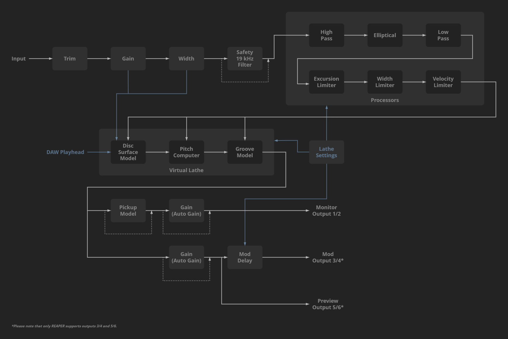
Signal Flow
Controls
Resetting Controls to Default Preset Values
Any control can be reset to its default preset position and value. This default position is the value that is set in the Default preset.
 | To reset a rotary control:
|
To reset a control value field:
|
Modifying Controls Using Text Entry
Many of the displayed control values have text boxes that can be modified directly.
 | To modify control values using text entry:
|
Control Functions
The control functions are split into nine sections:
- Host and Manual Modes
- Playhead Position Controls
- Disc Geometry and Position Information Controls
- Disc Cut Controls
- Processors Controls
- Lathe Controls
- Monitor Controls
- Disc Stats Window and Controls
- Groove Microscope Window and Controls
Host and Manual Modes
SimuLathe and Playhead Sync
SimuLathe’s advanced feature depend on the host’s playback position. This allows the plugin to analyze the incoming audio and build a map of the disc(s), in turn permitting precise prediction of the groove geometry and its space usage. The playhead’s position also has a significant effect on diameter losses, directly affecting the limitations and sound of the cutting and pick-up processes.
SimuLathe can Read the playhead position reported by the host, if provided. Note that some plugin hosts do not have a concept of playhead (see: Plugin Host Compatibility).
Cockos Reaper further allows SimuLathe to Write the playhead position.
If a host sync is not directly supported, SimuLathe offers a workaround based on automation. See chapter Playhead Sync Automation Workaround for more details on this workflow.
SimuLathe also offers a “Manual Sync” mode compatible with most hosts. This allows the operator to directly control the cutting-stylus position on disc. This is a great way to test and explore how audio material translates to a physical groove, and how it sounds at different locations on a record when converted back into audio by a pickup.
The Manual Sync mode is a great option for music producers and mastering engineers looking to test their decisions “against a disc”, and develop a good feel for the mechanisms at play. This mode allows you to move the cutting position freely and make virtual test cuts on different parts of a record while listening through the pickup simulation.
Tip: Manual mode is useful to hear how different the sound at the beginning of a record compares to the sound of its end. This helps with deciding which song is best to put last on a disc side and where you want the side to end.
Host
Host mode enables SimuLathe to operate in perfect sync with the DAW timeline, allowing it to follow the playhead location and make an accurate space consumption prediction of the cut. SimuLathe’s Disc Statistics and Groove Microscope waveform views can also take control of basic transport functions in supported host applications. The following transport functions can be performed within SimuLathe’s waveform views:
|
Manual
| Manual mode enables SimuLathe to operate in any DAW where playhead sync information with the plugin is unsupported. In this mode SimuLathe will ignore any playhead information from the DAW and process the audio regardless of its playback state. In Manual mode the disc surface playhead position is fixed and set by the Manual Position control which is displayed and adjusted in percentages. Note: The exact playhead position is calculated from the disc radius multiplied by the Progress value.* *In this case the radius is the distance from the modulation start to the modulation end. |
Playhead Position Controls
Playhead Position (Host Mode)
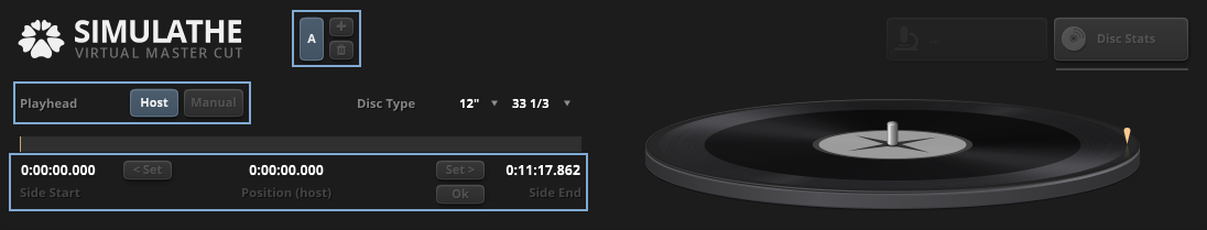
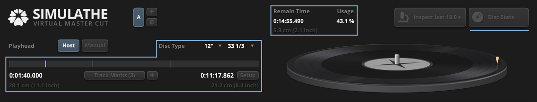
The highlighted upper left of the plugin contains the controls related to the DAW playhead position in Host mode.
In Host mode it’s required to set up the Side Start and Side End locations using their individual Set buttons for each Disc Side. This tells SimuLathe when the audio of a disc side starts and when it ends.
To create the Side Start and Side End locations for one side of an LP cut:
- Create a new session or project in your DAW.
- Create an audio track.
- Import audio files into the audio track in your preferred order with a gap between tracks.
- Insert the SimuLathe plugin on the audio track.
- Move the DAW playhead to the start of the first audio file then select the Add New Disc Side (+) button to create disc side 1 (A).
- Select the Set button for Side Start.
- Move the DAW playhead to the end of the last audio file then select the Set button for Side End.
- Select the Disc Time Confirmation (Ok) button to complete the disc time setup and close the setup panel.
SimuLathe now is able to simulate a real cut – space consumption gets calculated as audio passes through the plugin.
SimuLathe generates a disc surface geometry map that represents one disc side. This surface geometry map plots the diameter, excursion, width, velocity, and land properties onto the disc. The map also calculates space consumption. For the second disc side (up to eight sides are supported):
- Place the DAW playhead at the end of the last side 1 audio track with a gap in between.
- Import audio files into the audio track in your preferred order with a gap between tracks.
- Move the DAW playhead to the start of the first side 2 audio file then select the Add New Disc Side (+) button to create disc side 2 (B).
- Select the Setup button to open the Disc Time Setup panel.
- Select the Set button for Side Start.
- Move the DAW playhead to the end of the last side 2 audio file then select the Set button for Side End.
- Select the Disc Time Confirmation (Ok) button to complete the disc time setup and close the setup panel.
To create Track Marker locations:
- Move the DAW playhead to the beginning of a track.
- Select the Add New Track Marker button. The marker is created and appears in the track marker menu.
- Repeat the above steps for each additional track.
Playhead
| The Playhead mode selector enables Host mode by default. This mode syncs the playhead position to the host application if supported. |
Position (host)
| Position (host) displays the playhead location of the host application. The time scale format is set to Hours:Minutes:Seconds:Milliseconds. Tip: If you’re uncertain about host compatibility move the DAW playhead in the timeline and check if SimuLathe’s Position (Host) updates to the same location. |
Side Start
| Side Start displays the start point of the disc side based on the host application’s playhead. The time scale format is set to Hours:Minutes:Seconds:Milliseconds. The Set button is used to set up the start point of the disc side. |
Side End
| Side End displays the end point of the disc side based on the host application’s playhead. The time scale format is set to Hours:Minutes:Seconds:Milliseconds. The Set button is used to set up the end point of the disc side. The Disc Time Confirmation (Ok) button is used to complete the disc time setup and close the setup panel. |
Disc Side
| This area of the interface is used to manage the disc sides. SimuLathe creates a disc surface map which holds the information for one single disc side. |
| The Add New Disc Side (+) button creates a new disc side. Up to eight disc sides are supported and labelled A–H. |
| The Disc Side Selection button is used to select a single side of the disc. |
| The Delete Selected Disc Side button is used to remove the selected disc side. |
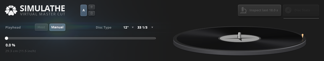
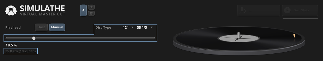
Playhead Position (Manual Mode)
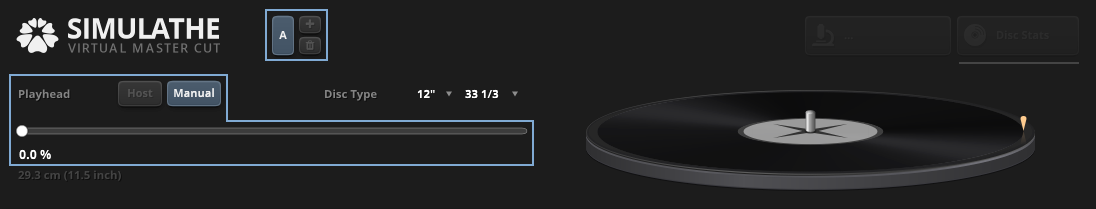
The highlighted upper left of the plugin contains the controls related to the DAW playhead position in Manual mode.
Playhead
| The Playhead mode selector should be set to Manual mode if playhead sync information with the plugin is unsupported by the host application. This will ignore all playhead location information. |
Manual Position
 | The Manual Position control is used to manually set the disc surface playhead position relative to the Disc Type (Disc Diameter). The value is displayed and adjusted in percentages. Tip: Use the Manual Position control to get an idea of how the material will perform at different diameters. |
Disc Side
 | This area of the interface is used to manage the disc sides. SimuLathe creates a disc surface map which holds the information for one single disc side. |
 | The Add New Disc Side (+) button creates a new disc side. Up to eight disc sides are supported and labelled A–H. |
 | The Disc Side Selection button is used to select a single side of the disc. |
 | The Delete Selected Disc Side button is used to remove the selected disc side. |
Disc Geometry and Position Information Controls
Disc Geometry and Position Information (Host Mode)
The highlighted controls of the plugin are related to the Disc Geometry and Position Information in Host mode.
SimuLathe generates a disc surface geometry map of the grooves for every disc side and is empty by default. This map gets filled during playback which is displayed in the Disc Map Fill progress bar. The surface map also gets refreshed each time the audio is played back. This process can be accelerated by committing an offline bounce/render.
Note: Certain added processes such as HP, LP, and elliptical filters will clear the generated map. These changes will turn segments of the Disc Map Fill progress bar red. SimuLathe will refresh and update the map during playback when these changes have been made.
 | The Disc Map Fill displays the progress of the disc map’s fill state. It’s primary use is to estimate space consumption and statistical visualizations. SimuLathe continuously analyzes the audio input and maps it onto the disc. These analyzed segments appear blue in the progress bar. Outdated segments will turn red. The red segments occur when changing lathe settings or certain preprocessor settings. Tip: Render the track (if supported by the host) to update the entire disc map. Tip: Double-click on the disc map progress bar to invalidate (indicated as red) the bar. This is useful when changing the incoming material on the fly (i.e. if the source got modified in one way or another). |
Disc Type
| Disc Type displays the disc diameter and disc rotation speed expressed in RPM (Revolutions Per Minute). Both the Disc Diameter and Disc RPM can be changed using their menus. |
 | The Disc Diameter menu allows you to select one of three available diameters. |
 | The Disc RPM menu allows you to select one of five available disc rotation speeds. |
Note: Modern cutting rooms do not strictly follow all historic standards, including the determination of the minimum diameter of 10″ records based on record speed. In the past, this decision was based on record speed, but today, the physical dimensions of the start of a 10″ record are still relevant. However, the RPM of the record no longer dictates the end of the lead out.
SimuLathe provides preset options for lead in and lead out in commercially used formats, such as 12″, 10″, and 7″ records, regardless of RPM. The only exception is 78rpm, which is not commonly used commercially today, but is available as a feature in SimuLathe.
Although SimuLathe does not offer presets for all historic standards, users are free to manually input them with a high degree of accuracy in the Lathe Calibration Settings.
Playhead Progress Bar

The Playhead Progress Bar displays the progression of the playhead on the disc and shows track mark locations. The progress bar also provides an overview of each content section start, end, and duration.
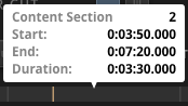 | Click any location in the progress bar to display an information overview of the content section number, start time, end time, and duration. |
Position
| Position displays the playhead location on the disc. The time scale format is set to Hours:Minutes:Seconds:Milliseconds. |
Pos Diameter
| Position Diameter displays the playhead diameter on the disc. This value is calculated from the playhead location to the end of the modulation area. The position diameter’s unit of measurement is set to cm/in. |
Duration
| Duration displays the total length of the audio on the disc. The time scale format is set to Hours:Minutes:Seconds:Milliseconds. |
Duration Diameter
| Duration Diameter displays the end diameter written on disc. |
Track Marks
  | Select the Track Marks button to open its menu for further options. |
| Select the Add New Track Marker button to create a new marker at the the playhead location. To create a Track Marker location:
|
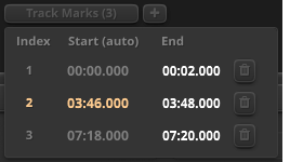 | The track marker menu offers further options to manually edit the markers. The menu is arranged into three columns:
|
| Select the Trash button in the menu to delete a marker. |
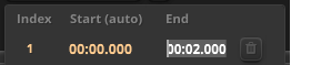 | The length of a track marker can be manually set by selecting its End value and entering a new time location. Note: Track Marks have a default length of 2 seconds. This can be changed in the Lathe Calibration panel using the Marker Length setting. |
Setup
| Select the Setup button to open the Disc Time Setup panel. |
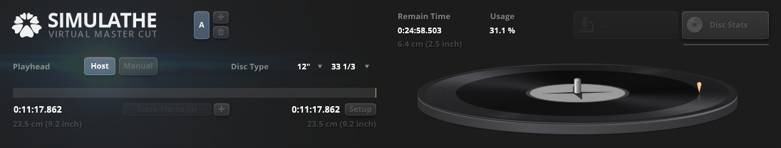
Usage
| Usage shows the total disc space consumption displayed as percent. Note: Disc space consumption is recalculated in real time when any Gain, Width, RPM, Disc size or Lathe Calibration changes occur. |
Remain Time
 | Remain Time displays how much time is left on the entire disc side until it is completely full. This is estimated from previously written material. The time scale format is set to Hours:Minutes:Seconds:Milliseconds. cm(inch) shows the remaining space on disc until the end of the modulation area. |
Disc Geometry and Position Information (Manual Mode)
The highlighted controls of the plugin are related to the Disc Geometry and Position Information in Manual mode.
Disc Type
| Disc Type displays the disc diameter and disc rotation speed expressed in RPM (Revolutions Per Minute). Both the Disc Diameter and Disc RPM can be changed using their menus. |
| The Disc Diameter menu allows you to select one of three available diameters. |
| The Disc RPM menu allows you to select one of five available disc rotation speeds. |
Note: Modern cutting rooms do not strictly follow all historic standards, including the determination of the minimum diameter of 10″ records based on record speed. In the past, this decision was based on record speed, but today, the physical dimensions of the start of a 10″ record are still relevant. However, the RPM of the record no longer dictates the end of the lead out.
SimuLathe provides preset options for lead in and lead out in commercially used formats, such as 12″, 10″, and 7″ records, regardless of RPM. The only exception is 78rpm, which is not commonly used commercially today, but is available as a feature in SimuLathe.
Although SimuLathe does not offer presets for all historic standards, users are free to manually input them with a high degree of accuracy in the Lathe Calibration Settings.
Position
 | The Position control is used to manually set the disc surface playhead position relative to the Disc Type (Disc Diameter and Disc RPM). The value is displayed and adjusted in centimeters/inches. Tip: Use this control to get an idea of how the material will perform at different diameters versus its Disc Diameter and Disc RPM. |
Disc Cut Controls

The highlighted center region of the plugin contains the Disc Cut Controls.
Input Gain Trim
| Input Gain Trim controls the global input gain. Note: Input trim changes are excluded from Bypass when enabled. |
Output Overload
| The digital Output Overload LED illuminates when the signal level at the output of the plugin reaches 0 dBFS which may be heard as distortion. This is a passive indicator so that the output is never clipped. Use the LED as a guide to reduce the input gain until it stops flashing. The illuminated LED can be cleared by clicking on it. |
Gain
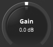 | Gain controls the lathe’s cutting level. The signal level has a substantial effect on both groove geometry and disc space consumption, as well as the resulting signal to noise ratio. As a result, gain is used to balance several conflicting interests. Tip: A general rule is to cut the disc as loud as possible, while keeping the disc usage adequate and the groove geometry within acceptable tracking conditions. Lower levels provide more material to fit onto the disc but at the cost of a lower signal to noise ratio. |
Width
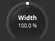 | Width controls the stereo width. The stereo width has a substantial effect on the resulting groove width/depth. As a result, width can be used to keep the groove width under control. Stereo width is displayed around the Width knob. |
Phase Correlation Meter
| The Phase Correlation Meter shows the stereo phase correlation. A low correlation translates into vertical movement of the cutting stylus. |
Preview Buffer
| The Preview Buffer displays the pitch computer’s preview buffer fill state. The preview buffer analyzes and computes the dynamic pitch signal by looking ahead. This is performed by delaying the audio path which imposes latency during playback. Note: This latency does not get reported to the host application unless Report Preview Latency is enabled. Note: In fixed pitch mode the pitch computer is not used. As a result, preview latency does not get added to the signal. |
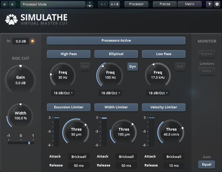
Processors Controls
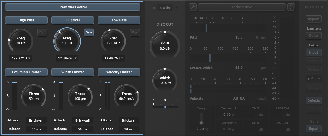
The highlighted left side of the plugin contains all controls for the preprocessors.
Processors Active

The Processors Active button is used to toggle the preprocessor section on and off.
High Pass
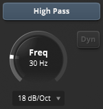 | The High Pass button is used to activate/deactivate the high pass filter. This filter can exhibit a strong effect on the resulting groove excursion (i.e., the lateral movement of the groove) – but only if such content is present in the audio and filtered with this filter. Freq controls the the high pass filter cutoff frequency. This attenuates all frequencies below the displayed rate while letting frequencies above it pass through. The High Pass Slope control sets the slope for the filter from the selected frequency. The slope values provided are 12 dB, 18 dB, 24 dB, 48 dB, or 72 dB per octave. The DYN button activates a dynamic function of the high pass filter when the filter is primarily used to reduce excursion/space consumption. In this instance the filter should perform as ‘in-audible’ as possible while also being efficient as necessary. This intelligent function reads the groove geometry and weakens the filter whenever space allows. This results in reduced low-end filtering of the audio while gaining more space on disc. |
Elliptical
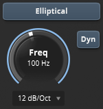 | The Elliptical button is used to activate/deactivate the elliptical filter. This controls the stereo width at low frequencies. It can affect the resulting groove width but only if such content is present in the audio. Freq controls the the elliptical high pass filter cutoff frequency. This attenuates all frequencies below the displayed rate while letting frequencies above it pass through. The Elliptical High Pass Slope control sets the slope for the filter from the selected frequency. The slope values provided are 3 dB, 6 dB, 12 dB, 18 dB, or 24 dB per octave. The Elliptical High Pass Dynamic button dynamically detects and “shifts” frequencies filtered in the side-channel to the mid-channel to maintain the overall frequency spectrum of the audio content. |
Low Pass
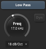 | The Low Pass button is used to activate/deactivate the low pass filter. This filter has a moderate effect on the resulting groove velocity. Freq controls the the low pass filter cutoff frequency. This attenuates all frequencies above the displayed rate while letting frequencies below it pass through. The Low Pass Slope control sets the slope for the filter from the selected frequency. The slope values provided are 6 dB, 12 dB, 18 dB, 24 dB, 48 dB, or 72 dB per octave. The Low Pass Dynamic button is used to activate/deactivate a dynamic bypass of this filter on low level signals. |
Excursion Limiter
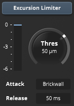 | The Excursion Limiter button is used to activate/deactivate the limiter for lateral excursion. Excursion is a result of cutting-level post RIAA encoding curve. The Excursion Limiter Gain Reduction meter shows the amount of gain reduction being applied to the incoming signal in dB. The Excursion Limiter Threshold sets the level that the signal must exceed to trigger the limiting. Signals above this threshold level will be compressed, while signals below it will remain unaffected. The excursion limiter’s threshold value is represented as µm or mil. The Excursion Limiter Attack Time sets the rate at which the gain is reduced after the signal crosses the threshold level. The attack time ranges from brickwall limiting (fastest attack time) to 10.0 ms (slowest attack time). The Excursion Limiter Release Time sets the duration of time taken for the limiter to deactivate after the signal drops below the threshold level. The release time ranges from 1.0 ms (fastest release time) to 2.0 sec (slowest release time). The Excursion Limiter has a hidden built-in threshold: 150 µm. Gain reduction derived from crossing this threshold is always applying brickwall limiting (attack time is not applied). Tip: Excursion greater than initial width can cause unstable pickups to skip out of the groove, especially at high cutting levels. Excursion is very much related to low frequency content. Slight changes in the High Pass Filter may have a big influence on the Excursion Limiter. |
Width Limiter
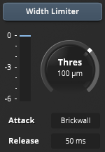 | The Width Limiter button is used to activate/deactivate the groove width limiter. Groove width is a result of the width control of the lathe and vertical excursion due to the stereo level of the audio. This limiter not only reduces stereo/side content of the audio signal, but also intelligently links to the mono/mid content to minimize negative effects in the stereo field. The Width Limiter Gain Reduction meter shows the amount of gain reduction being applied to the incoming signal in dB. The Width Limiter Threshold sets the level that the signal must exceed to trigger the limiting. Signals above this threshold level will be compressed, while signals below it will remain unaffected. The width limiter’s threshold value is represented as µm or mil. The Width Limiter Attack Time sets the rate at which the gain is reduced after the signal crosses the threshold level. The attack time ranges from brickwall limiting (fastest attack time) to 10.0 ms (slowest attack time). The Width Limiter Release Time sets the duration of time taken for the limiter to deactivate after the signal drops below the threshold level. The release time ranges from 1.0 ms (fastest release time) to 2.0 sec (slowest release time). Tip: Width values above 100µm (lacquer cut) or 65µm (DMM) are potentially risky. |
Velocity Limiter
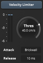 | The Velocity Limiter button is used to activate/deactivate the velocity limiter which allows it to specify a top velocity of the stylus (it is also the PB stylus velocity – and even more so as the cutting stylus has almost no issue with high velocity, but the PB stylus has). Signals above the threshold will have a dynamic high frequency attenuation applied. In extreme cases, full signal attenuation will be applied to protect the cutter head. The Velocity Limiter Gain Reduction meter shows the amount of gain reduction being applied to the incoming signal in dB. This meter contains two bars. The right bar represents high frequency attenuation. The left bar represents low frequency attenuation. The Velocity Limiter Threshold sets the level that the signal must exceed to trigger the limiting. Signals above this threshold level will be compressed, while signals below it will remain unaffected. The velocity limiter’s threshold value is represented as cm/sec. The Velocity Limiter Attack Time sets the rate at which the gain is reduced after the signal crosses the threshold level. The attack time ranges from brickwall limiting (fastest attack time) to 10.0 ms (slowest attack time). The Velocity Limiter Release Time sets the duration of time taken for the limiter to deactivate after the signal drops below the threshold level. The release time ranges from 1.0 ms (fastest release time) to 2.0 sec (slowest release time). The Velocity Limiter has two hidden built-in thresholds: 105 cm/sec for peaks and 28.5 cm/sec for continuous action (50 ms smoothing window size). Gain reduction derived from crossing these thresholds is always applying brickwall limiting (attack time is not applied). Tip: Fast peak velocity metering was not possible until SimuLathe and is new to the cutting world. We are still researching good values for save cuts. At this moment we can assume that very short signals up to 60-70cm/s and maybe above (depending on the condition of your cutting amp and cutter head) are not unusual for a very hot cut. Audible distortion on some pickups happens much earlier, especially with longer signals. You can use the Dynamic function of the Low Pass filter along with the Velocity Limiter to achieve smoother control while still protecting your equipment reliably. |
Lathe Controls
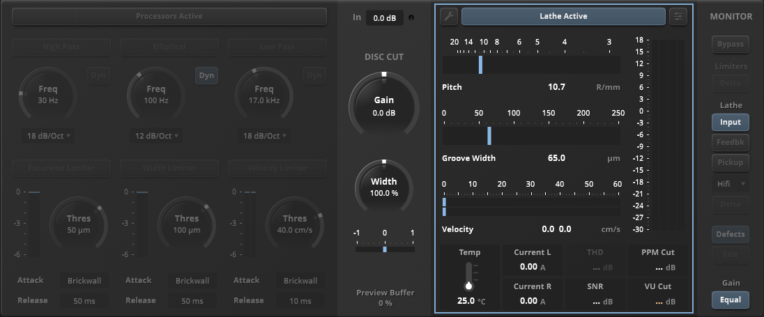
The highlighted right side area of the plugin contains the Lathe Meters, Cut Configuration panel, and Lathe Calibration panel.
Lathe Active

The Lathe Active button is used to toggle the virtual lathe section on and off. The lathe is bypassed when inactive. This is equivalent to the Monitor being set to Input, with the difference that an inactive virtual lathe also reduces CPU load and imposes less latency. The Processors always work independently from the lathe status.
Cut Configuration
| Select the Cut Configuration button to access individual cut configuration parameters. |
Cut Configuration Settings
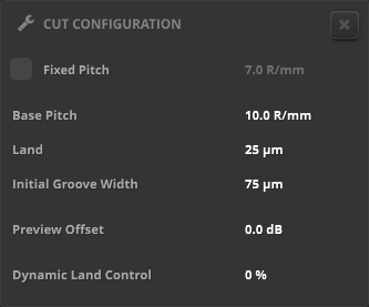
The Cut Configuration panel offers fundamental configuration options that are typically changed for any disc side.
- Fixed Pitch turns off the dynamic pitch system and depth control, and drives the cutter-head from the outside to the inside at a fixed speed regardless of the cutting level.
- Base Pitch is the initial/unmodulated speed at which the dynamic pitch system drives the cutter-head from the outside to the inside. It defines how many grooves are packed on the record. Longer sides need more grooves. It is measured in ‘lines per inch’ / ‘Rillen pro Millimeter’. Typical range: 500LPI – 20R/mm…250LPI – 10R/mm. Typical value for LP: 350LPI – 14R/mm. The Base Pitch, Initial Groove Width, and Land interact.
- Land is the initial/unmodulated distance between grooves. More land requires more space. A minimum land is needed to compensate for the unevenness of the master lacquer to avoid over-cuts and for slight variations in pitch control of the lathe in the cutting room. Minimum reasonable value: 0.3mil – 5µm. Greater land helps to protect the groove from pre- and post-echoes as well as surface damage (scratches) and gives more protection from possible errors of the pitch system. Typical value: 0.5mil – 15µm. The Base Pitch, Initial Groove Width, and Land interact.
- Initial Groove Width is the initial/unmodulated width at which the pitch system cuts a groove. Wider grooves require more space. Typical range: 2mil – 50µm to 3.5mil – 90µm. Typical value for LP: 2.5mil – 60µm. The Base Pitch, Initial Groove Width, and Land interact.
- Preview Offset is the level offset set in dB for the dynamic pitch system. It can be used with a positive offset to fill sides that are very short. Negative offsets can be used to reduce space consumption (especially with greater land settings).
- Dynamic Land Control reduces the initial land value for the given percentage (depending on level). This function is used to save disk space. It reduces land on louder parts of the record where pre- and post-echoes are masked. Note: This setting must match with the real cutting lathe that makes the master-cut.
Tip: Any settings value can be reset to its default position. To reset a settings value:
- Alt-click (Windows) or Option-Click (macOS) directly on the value.
Lathe Calibration
| Select the Lathe Calibration button to access the lathe calibration parameters. |
Lathe Calibration Settings
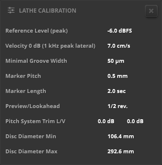
The Lathe Calibration panel offers advanced configuration options for further lathe adjustments.
- Reference Level (peak) is the digital level of the calibration tone (1kHz sine) as used on cutting lathes to calibrate the cutting level to ‘unity gain’ or ‘0 VU’. Typical range: -18 – 0 dBFS. This setting must match with the real cutting lathe that makes the master-cut.
- Velocity 0 dB (1 kHz peak lateral) is the velocity of the calibration tone as used on cutting lathes to calibrate the cutting level to ‘unity gain’ or ‘0VU’. This value comes from the reference test-record used during calibration. Most widely used: ‘NAB’ or ‘Ultimate Analog Test Record’ 7 cm/s peak to peak lateral. This setting must match with the real cutting lathe that makes the master-cut.
- Minimal Groove Width is the minimal width setting of the automatic width/depth control calibration of the lathe. It defines the minimum allowable groove width. Systems with no depth control will display 0. Typical values for modern lathes are 55µm. This setting should match with the real cutting lathe that makes the master-cut.
- Marker Pitch is the speed at which the pitch system is calibrated to run during track marks. Typical range: 0.8 – 1.15mm (31 – 45mils). Typical value 0.5mm (about 0.02 in). Greater values result in wider/more visible track marks. This setting should match with the real cutting lathe that makes the master-cut.
- Marker Length is the time to which the pitch system is calibrated to run with the Marker Pitch during track marks. Typical range: 0.3 – 2 sec. Typical value 1 sec. Greater values result in longer/more visible track marks. This setting should match with the real cutting lathe that makes the master-cut.
- Preview/Lookahead is the preview look-ahead of the pitch system set in revolutions. Typical range: 1/2, 9/16, or 6/10. Typical value: 1/2. This setting should match with the real cutting lathe that makes the master-cut.
- Pitch System Trim L/V are offsets that can be used to match SimuLathe’s lateral and vertical pitch gains with those of an existing lathe system’s calibrations. Typical values: +-0 dB. These settings must match with the real cutting lathe that makes the master-cut.
- Disc Diameter Min is the innermost part of the disc that can be cut. This setting must match with the real cutting lathe that makes the master-cut.
- Disc Diameter Max is the outermost part of the disc that can be cut. This setting must match with the real cutting lathe that makes the master-cut.
Tip: Any settings value can be reset to its default position. To reset a settings value:
- Alt-click (Windows) or Option-Click (macOS) directly on the value.
Output
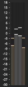 | The Lathe Output Meter displays the average and peak levels of the selected (Monitor) output signal. Click the meter to reset the min/max hold region. Right-click the output meter to select between digital (rms vs peak) or analogue meter modes (vu vs ppm) in the context menu. Note: Analog meters are preferred and used in disc mastering studios. |
Pitch
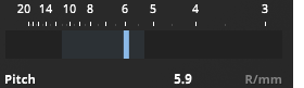 | The Pitch meter displays the speed of the cutter-head moving toward the disc center. The goal of this movement is to make sufficient room versus the previous revolution’s groove. Pitch can either be constant or variable. Most modern cutting lathes support some form of variable pitch to optimize disc space consumption and to make sure grooves don’t overcut each other. They’ll also have a variable width control to prevent lift-offs. Note: The faster the pitch the more disc space will be used. Tip: Pitch is displayed as R/mm (Rillen pro Millimeter) or LPI (Lines per inch). The distance is measured to the end diameter of the record. Click the meter to reset the min/max hold region. Right-click the meter to choose the Lines or Distance scale from the context menu. |
Groove Width
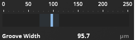 | The Groove Width meter displays the groove width being equivalent to twice the groove depth (this is due to the 90° angle of the groove). Click the meter to reset the min/max hold region. |
Velocity
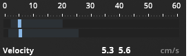 | The Velocity meter displays the groove velocity. High groove velocity translates to a sharp and complex groove geometry. This stresses both the cutter-head and the pickups attempting to follow the groove. It is advised to keep high velocity regions as short as possible and only as loud as necessary. If exceeding 35 cm/sec a cutter-head will start to heat disproportionally and this might, in extreme cases, trigger the safety circuit breakers of the cutting system. A high velocity will drive most pickups into distortion. Click the meter to reset the min/max hold region. Tip: Fast peak velocity metering was not possible until SimuLathe and is new to the cutting world. We are still researching good values for save cuts. At this moment we can assume that very short signals up to 60-70cm/s and maybe above (depending on the condition of your cutting amp and cutter head) are not unusual for a very hot cut. Audible distortion on some pickups happens much earlier, especially with longer signals. |
Temp
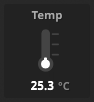 | Cutter-head Temperature displays its current temperature. Temperatures beyond 200° C will force the circuit breakers to engage. This is to prevent the valuable cutter-head from being damaged. As every cutting system and cutter-head is different, this value can only be a coarse estimation. |
Current
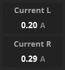 | Head Current displays the current at both the head’s left and right channels. Currents exceeding 1.5 amperes will force the circuit breakers to engage. This is to prevent the valuable cutter-head from being damaged. Since this is different from cutting room to cutting room, this is only a course estimation. |
THD
 | The THD meter measures the total harmonic distortion for the selected pickup model. If the lathe monitor has its Input or Feedback enabled then the meter displays the amount of groove-self-erase from the cutting-stylus due to high velocity. |
SNR
 | The SNR meter displays the signal to noise ratio for the selected pickup model. |
PPM Cut
 | PPM Cut displays the peak value of the cutting level. |
VU Cut
 | VU Cut displays the VU value of the cutting level. |
Circuit Breaker Warning
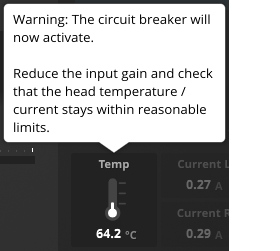 | The Circuit Breaker Warning displays when the circuit breakers get triggered. The circuit breakers will engage during the following conditions:
Note: Do not use SimuLathe circuit breakers instead of real circuit breakers. The Virtual Circuit Breaker submenu offers further behavior options for its warning indicator. These settings are in the Processing Quality menu located on the Toolbar. Note: The following occurs if the Virtual Circuit Breaker is set to Action and gets triggered:
|
Monitor Controls
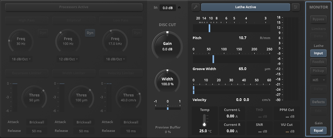
The highlighted far right side of the plugin contains the Monitor, Lathe, and Pickup controls.
Bypass
| Enable bypass to pass the input signal through SimuLathe without any processing. Bypass is latency compensated. Note: Input Gain Trim changes are excluded from Bypass when enabled. |
Limiters Delta
 | Select the Limiters Delta button to monitor the audio material added or removed by the preprocessor limiter section. This is useful for fine tuning the limiters by listening to the audio material that gets affected the most. |
Input
| Select the Input button to route the audio after the processors directly to the output of the plugin. Input monitor has no preview latency. |
Feedback
| Select the Feedback button to route the signal return from the cutter-head during the master-cut. This has the same latency as the pickup models. Tip: This monitor is good for doing A/B comparisons with the different pickup models. |
Pickup
| Enable the Pickup button to activate the pickup simulation for audible inspection of the virtual lacquer. |
HiFi
| Select HiFi to enable the MicroRidge pickup model. |
MidFi
| Select MidFi to enable an average elliptical pickup model. |
Club
| Select Club to enable an elliptical pickup model often used by DJs. |
Delta
| Enable the Delta button to monitor the audio changes of the different pickup models. |
Defects
| Select the Defects button to enable all playback defects. |
Edit
| Select the Edit button to access the Playback Defects panel. |
Playback Defects
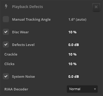
The Playback Defects settings provide further adjustable options related to the following playback defects:
- Manual Tracking Angle overrides the automatic tracking angle with a manual tracking angle. This is useful for previewing the effect that a wrong tracking angle would have on playback. The angle value is displayed and adjusted in degrees.
- Disc Wear controls the amount of groove wear. The value is displayed and adjusted in percent.
Tip: Disc Wear creates subtle to massive distortion. This happens when records are played very often, especially with less than optimum pick-ups. A value of 10% can give some realistic feeling of a test-pressing. Experiment with this value to find what works best for you. Listen to your cut in various states of aging – this might change some of your decisions regarding the high frequency response of a record significantly. - Defects Level activates the dust particles model and provides setting a -/+ 20 dB level relative to the factory default.
- Crackle amount controls the density of crackles. The value is displayed and adjusted in percent.
- Clicks amount controls the density of clicks. The value is displayed and adjusted in percent.
- System Noise activates the system noise model and provides setting a -/+ 20 dB level relative to the factory default.
- RIAA Decoder provides bypassing the RIAA Decoder and allows for monitoring the signal as it hits the cutting system.
- Normal: Standard RIAA decoding.
- Placement: The signal as seen by the pitch computer.
- Velocity: The signal as seen by the cutting stylus.
Tip: Any settings value can be reset to its default position. To reset a settings value:
- Alt-click (Windows) or Option-Click (macOS) directly on the value.
Equal
 | Enable the Equal button to provide automatic gain compensation for all level changes except Input Gain Trim. |
Disc Stats Window and Controls
Disc Stats
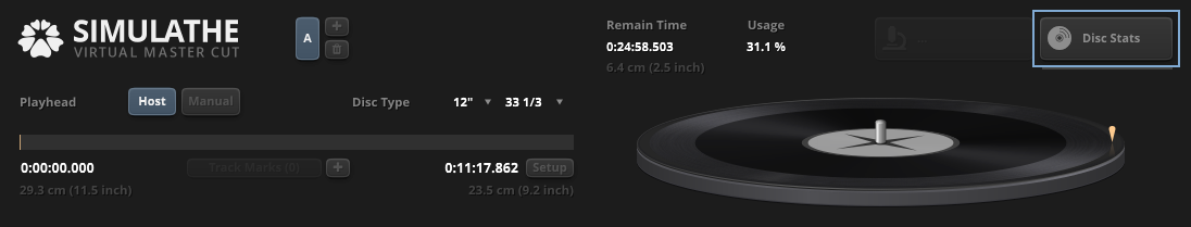
| The upper right region of the plugin contains the Disc Stats button. Select this button to access the Disc Stats Window and Controls. |
Disc Stats Window

The Disc Stats window displays a visual representation of the disc surface map. It also provides navigation control, heat map visualizations, disc statistics, and a waveform view.
Disc Statistics Scope

The Disc Statistics Scope provides navigation control and visualization of the disc surface. The scope also shows the disc surface in the form of various heat maps.
To navigate the disc with a mouse:
- Click and drag vertically to rotate the disc.
- Use the scroll wheel to zoom in and out of the disc.
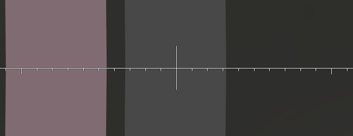
To temporarily move the reticle marker horizontally:
- Alt-click and drag the reticle marker left or right.
Tip: Use this tool to manually measure groove features, such as excursion, width, velocity, and land, independently from the values displayed in the Disc Statistics Info Area.
Reticle is used to display one of the following reticle markers in the Disc Statistics Scope:
|
 | Magnification is used to adjust the Disc Statistics Scope zoom level. At a viewing angle of 90° the magnification is achieved by controlling the focal length. This mode has almost no perspective distortion. At all other angles the magnification is performed as a dolly zoom, which moves the camera towards the disc. The Magnification buttons are used to view the disc at the following magnification levels:
|
| Zoom provides a top-down only view of the disc. Use the Magnification to adjust the disc scope zoom level. |
| Dolly provides a camera angle view of the disc. Use Cam Angle to adjust the disc scope viewing angle. |
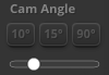 | Cam Angle is used to adjust the Disc Statistics Scope viewing angle. The Cam Angle buttons are used to view the disc at the following angles:
|
Disc Statistics Info Area
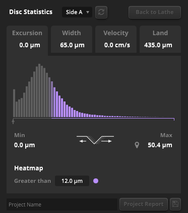
The Disc Statistics Info Area provides an overview of various statistics for the selected disc and other additional functions.
| The Disc Side button is used to select a single side of the disc when multiple disc sides are created. Up to eight disc sides (labelled A–H) can be selected from. |
| Select the Disc Statistics Refresh button to update the disc statistics according to the latest audio/disc data. |
| Select Back to Lathe to close the Disc Stats window and return to the main view. |
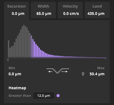
The Disc Statistics Info Area tabs show a visualization overview of the playhead position, groove excursion, width, velocity, and land width for the selected disc.
 | The Excursion tab shows the disc’s groove excursion as a heat map. |
 | The Width tab shows the disc’s groove width as a heat map. Excessively wide grooves (above 100µm) may cause issues in later disc reproduction processes. |
 | The Velocity tab shows the disc’s groove velocity as a heat map. Too much velocity stresses both the cutter-head and the pickup during playback. This usually causes distortion during these phases. Tip: Fast peak velocity metering was not possible until SimuLathe and is new to the cutting world. We are still researching good values for save cuts. At this moment we can assume that very short signals up to 60-70cm/s and maybe above (depending on the condition of your cutting amp and cutter head) are not unusual for a very hot cut. Audible distortion on some pickups happens much earlier, especially with longer signals. |
 | The Land tab shows land (the space between groove) as a heat map. Land becomes zero or even negative when grooves briefly touch or overcut. Tip: Land below 5µm cannot reliably be controlled on a hardware cutting system. It is not recommended to go to 0µm land in SimuLathe if you want no overcuts in the real world. |
| Pushpins assign minimum and maximum values and operate like shortcuts to the disc’s hotspots. Click them multiple times to cycle through two additional minimum or maximum values. Tip: These pushpin hotspots are useful for test-cuts. |

The Project Report area lets you create, view, and export vital settings, measurements, and time stamps needed for the disc mastering engineer.
Project Name allows for naming the project that will be used in the report.
The Project Report button allows for viewing the project report. The document is created in the HTML format and will open in your default browser.
Select the Export Project Report button to export and save the document in the HTML format.
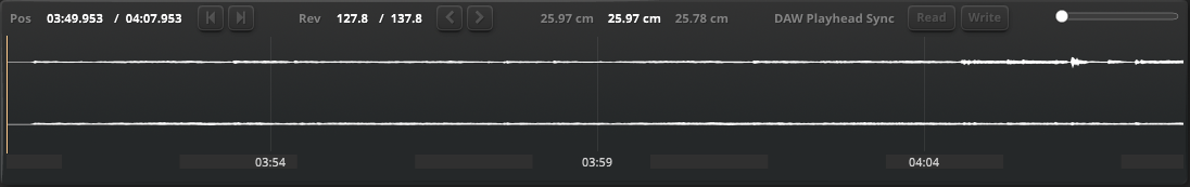
Disc Statistics Waveform View

The Disc Statistics Waveform View displays a waveform representation of the data from the disc surface map. Other information such as position, disc revolutions and playhead sync are provided, along with zoom, navigation control, and a timebase ruler.
To navigate directly in the waveform view using the mouse, do one of the following:
- Click a location in the waveform to move the playhead.
- Click and drag horizontally anywhere in the waveform to move the playhead.
- Click and drag the horizontal scroll bar located at the bottom of the Disc Statistics Waveform View.
Note: Scroll bar visibility is hidden at the maximum zoom out level and appears when zooming in the waveform.
To magnify the waveform horizontally using the mouse scroll wheel:
- Hover the mouse over a location in the waveform.
- Move the scroll wheel up or down. Magnification will move toward and from the playhead location.
| Pos (Position) displays the playhead location on the waveform. The time scale format is set to Hours:Minutes:Seconds:Milliseconds. The Jump to Start button moves the playhead to the waveform start. The Jump to End button moves the playhead to the wave form end. |
| Rev (Revolutions) displays the disc revolutions. The left value displays the amount of disc revolutions from the start to the playhead location. The right value displays the total amount of disc revolutions on the disc. The Jump to Previous Groove button moves the playhead to the previous groove on the disc surface. This will move the playhead location to the right in the waveform view. The Jump to Next Groove button moves the playhead to the next groove on the disc surface. This will move the playhead location to the left in the waveform view. |
| Diameter indicator shows the start diameter, playhead diameter, and end diameter on the disc surface. |
 | Flyby mode provides a continuous movement of the playhead. Shift-click on either Jump to Previous/Next Groove buttons to activate Flyby mode. The Flyby slider will appear above the DAW Playhead Sync Read and Write buttons and is used to control the speed of the movement. This is a useful tool to help understand how the pickup-stylus is tracking the groove. Note: Flyby mode is only available when both DAW Playhead Sync Read and Write buttons are disabled. |
| DAW Playhead Sync defines how the playhead gets synchronized between SimuLathe and the host application. Playhead Read allows the host application to control the Disc Statistics Waveform View playhead. Playhead Write allows SimuLathe to control the host application’s playhead. |
| The Waveform Zoom slider adjusts the magnification level of the waveform. The magnification level will move toward and from the playhead location in the waveform. |
The Timebase Ruler displays two different time measurement formats:
|
Groove Microscope Window and Controls
Inspect Last

| The highlighted button in the upper right area of the plugin is the Inspect Last button. Select the Inspect Last button to access the Groove Microscope Window and Controls. The Inspect Last button also displays how much of the groove has been inspected (up to 18 seconds) by the virtual microscope during playback. |
Groove Microscope Window
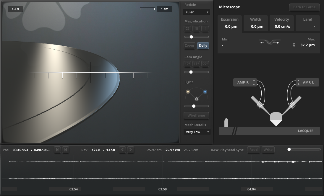
The Groove Microscope window displays a visual representation of the inspected groove. It also provides navigation control, lighting options, disc statistics, an illustration of the cutter-head operation, and a waveform view.
Virtual Groove Microscope
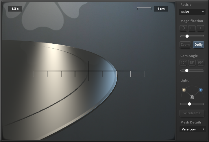
The Virtual Groove Microscope provides navigation control and visualization of the inspected groove. The scope also allows for adjusting the light source and light field.
To navigate the disc with a mouse:
- Click and drag vertically to rotate the disc.
- Use the scroll wheel to zoom in and out of the disc.
To temporarily move the reticle marker horizontally:
- Alt-click and drag the reticle marker left or right.
Tip: Use this tool to manually measure groove features, such as excursion, width, velocity, and land, independently from the values displayed in the Groove Microscope Info Area.
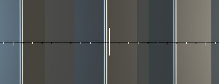
Reticle is used to display one of the following reticle markers in the Groove Microscope:
|
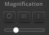 | Magnification is used to adjust the Groove Microscope view level. At a viewing angle of 90° the magnification is achieved by controlling the focal length. This mode has almost no perspective distortion. At all other angles the magnification is performed as a dolly zoom, which moves the camera towards the disc. The Magnification buttons are used to view the disc at the following magnification levels:
|
| Zoom provides a top-down only view of the disc. Use the Magnification to adjust the groove microscope scope zoom level. |
| Dolly provides a camera angle view of the disc. Use Cam Angle to adjust the groove microscope viewing angle. |
 | Cam Angle is used to adjust the Groove Microscope viewing angle. The Cam Angle buttons are used to view the disc at the following angles:
|
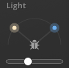 | Light allows for changing the Virtual Groove Microscope light sources and light field. Click in this region to open the Light Sources menu. The Light Field slider adjusts the microscope’s light field. This uses two symmetrically arranged light sources with adjustable angles to the object of interest. Angles below 45° generate a dark field with bright details. Angles greater than 45° produce a bright field with details appearing dark |
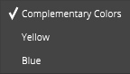 | The Light Sources menu offers the following for adjusting the Virtual Groove Microscope light sources:
|
| The Wireframe button changes the disc groove display mode to a wireframe view. |
| Mesh Details sets the level of detail for the disc groove. Lower detail levels will compromise high frequency accuracy against the GPU load. This will still provide an accurate picture of the groove width/depth. The highest detail level will match the internal sample rate and permits inspecting high velocity regions in all detail. The following mesh detail levels are available from the menu:
|
Groove Microscope Info Area
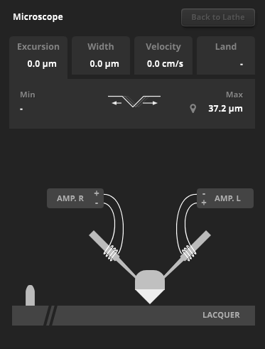
The Groove Microscope Info Area provides a statistics overview and cutting stylus illustration for the inspected groove.
| Select Back to Lathe to close the Groove Microscope window and return to the main view. |
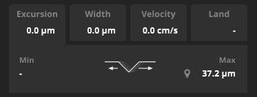
The Groove Microscope Info Area tabs show a visualization overview of the playhead position, groove excursion, width, velocity, and land width for the inspected groove.
| Pushpins assign minimum and maximum values and operate like shortcuts to the groove microscope view hotspots. Click them multiple times to cycle through two additional minimum or maximum values. |
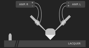
The Cutting Stylus illustrates the cutter-head in operation.
Tip: Click the cutter-head illustration to reset its groove history.
Groove Microscope Waveform View
The Groove Microscope Waveform View displays a waveform representation of the groove’s audio input as a ‘Sum and Difference’ (i.e., Mid/Side) view. Other information such as position, disc revolutions and playhead sync are provided, along with zoom, navigation control, and a timebase ruler.
To navigate directly in the waveform view using the mouse, do one of the following:
- Click a location in the waveform to move the playhead.
- Click and drag horizontally anywhere in the waveform to move the playhead.
- Click and drag the horizontal scroll bar located at the bottom of the Groove Microscope Waveform View.
Note: Scroll bar visibility is hidden at the maximum zoom out level and appears when zooming in the waveform.
To magnify the waveform horizontally using the mouse scroll wheel:
- Hover the mouse over a location in the waveform.
- Move the scroll wheel up or down. Magnification will move toward and from the playhead location.
| Pos (Position) displays the playhead location on the waveform. The time scale format is set to Hours:Minutes:Seconds:Milliseconds. The Jump to Start button moves the playhead to the waveform start. The Jump to End button moves the playhead to the wave form end. |
| Rev (Revolutions) displays the disc revolutions. The left value displays the amount of disc revolutions from the start to the playhead location. The right value displays the total amount of disc revolutions on the disc. The Jump to Previous Groove button moves the playhead to the previous groove on the disc surface. This will move the playhead location to the right in the waveform view. The Jump to Next Groove button moves the playhead to the next groove on the disc surface. This will move the playhead location to the left in the waveform view. |
| Diameter indicator shows the start diameter, playhead diameter, and end diameter on the disc surface. |
| Flyby mode provides a continuous movement of the playhead. Shift-click on either Jump to Previous/Next Groove buttons to activate Flyby mode. The Flyby slider will appear above the DAW Playhead Sync Read and Write buttons and is used to control the speed of the movement. This is a useful tool to help understand how the pickup-stylus is tracking the groove. Note: Flyby mode is only available when both DAW Playhead Sync Read and Write buttons are disabled. |
| DAW Playhead Sync defines how the playhead gets synchronized between SimuLathe and the host application. Playhead Read allows the host application to control the Disc Statistics Waveform View playhead. Playhead Write allows SimuLathe to control the host application’s playhead. |
| The Waveform Zoom slider adjusts the magnification level of the waveform. The magnification level will move toward and from the playhead location in the waveform. |
The Timebase Ruler displays two different time measurement formats:
|
Toolbar
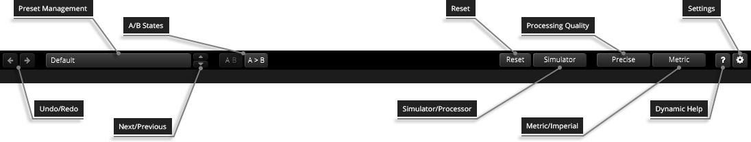
Undo/Redo
 | Use the undo/redo buttons to recall previous/next parameter changes. The exact event is shown in a tool tip. Please note that certain parameter changes are not tracked by this function (e.g. “Bypass”). |
Preset Management

The preset drop-down list offers quick access to factory settings and user presets.
| The next/previous buttons allow you to cycle through the presets. |
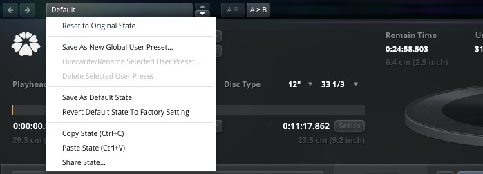
Advanced preset management options are available from the context menu (Right-click).
Reset to Original state resets the currently active preset to its original state.
Save As New Global User Preset opens a dialog used to create User Presets. Note that these presets persist across sessions and DAWs (presets are saved on your machine). The total amount of user presets is limited to 20.
Overwrite/Rename Selected User-Preset allows to overwrite or rename presets.
Delete Selected User Preset allows to delete the current user preset.
Save As Default State replaces the plugins’ default preset with the current parameter state.
Revert Default State To Factory Setting deletes an overwritten default state.
Copy State (Ctrl+C) copies the current control states to the clipboard. This allows for applying control states (i.e. “presets”) across plugin instances and plugin hosts by using the Paste State command.
Paste State (Ctrl+V) pastes the control states from the clipboard.
Share State opens a dialog with additional preset sharing options via e-mail or internet forums.
A/B Control
| A/B allows to compare two alternative parameter states. |
| A>B and B<A copies one state to the other. |
Reset
|
Simulator/Processor
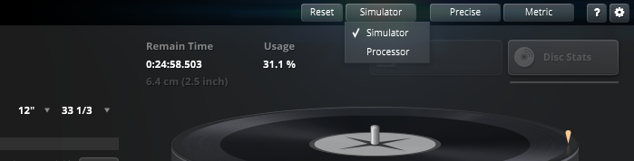
The Simulator/Processor submenu allows you to select either Simulator or Processor mode.
Simulathe’s full range of features are enabled by the Simulator mode. This mode is ideal for disk authoring and quality control, or for creating audible test cuts. However, it requires a substantial amount of resources to operate, including memory, CPU, and GPU.
The Processor mode enables a lightweight preprocessor exclusive mode. This mode is ideal when using Simulathe as a disk mastering preprocessor, as it bypasses most statistical data collection and hides unnecessary user interface elements.
Note: Modifying any control in Processor mode will change its identical control in Simulator mode, and vice versa. Controls for both modes are adjusted simultaneously and maintain parity between them, including disc side selection changes.
Processing Quality
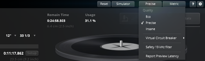
SimuLathe Cut offers three different processing quality modes:
- Eco – An economic CPU efficient mode used when CPU processing is limited.
- Precise – The default high fidelity processing mode.
- Insane – A very high quality processing mode which increases CPU load. Use it when CPU processing is abundant.
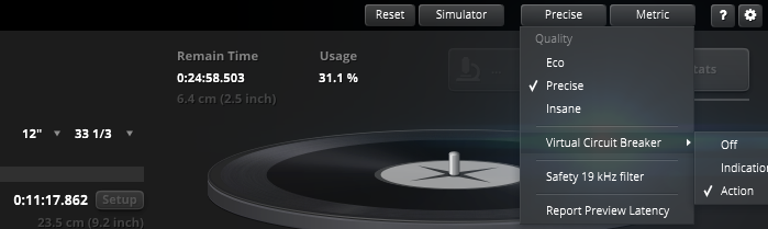
The Virtual Circuit Breaker submenu offers further options for its warning indicator.
- Off – Prevents the warning indicator from displaying when the circuit breaker gets triggered.
- Indication – Displays the warning indicator when the circuit breaker gets triggered. Note: To re-enable the warning indicator make the plugin inactive (offline) then active (online) again.
- Action – Displays the warning indicator when the circuit breaker gets triggered, stops the cutting process, mutes the cartridge model playback if enabled, and attenuates the monitor feedback signal if enabled.Note: To re-enable the Action functions make the plugin inactive (offline) then active (online) again.
Safety 19KHz Filter protects the cutter head from potentially dangerous high frequencies outside the typical range of hearing when using high sample rates.
Report Preview Latency allows the host to compensate for the latency caused by the pitch computer’s Preview Buffer.
Metric/Imperial
| The metric/imperial button allows you to use either metric units or imperial units. Note: Disc Type is always displayed in inches. Velocity is always displayed as cm/s. These are international standards in all countries. |
Help
| The dynamic help mode offers detailed information about the various elements of the user interface. Click “?” to activate the online help and move the mouse cursor over the control of interest. A small info bubble will appear displaying the function and details of the item. |
Settings
| The settings button opens a dialog which gives control over additional plugin options. |
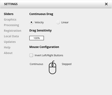
Slider allows for changing the behavior of knobs and control points in response to the mouse. Under Continuous Drag, knob and controller movement relies on mouse speed when Velocity is enabled. When Linear is enabled, knob and controller movement is proportional to mouse movement. Drag Sensitivity sets the linear sensitivity of the knob and controller movement further.
Plug-in controls, knobs, and control points can be adjusted using Left-click & drag (Continuous) and Right-click & drag (Stepped) by default. Mouse Configuration swaps the Continuous and Stepped behaviors between the left and right mouse buttons when selecting Invert Left/Right Buttons. Note that the default stepped values can be customized via the product configuration file. See “Local data” below for instructions on how to access this file.
Graphics allows for changing the interface size to a fixed percentage value between 100%, 125% and 150%.
Processing shows the plug-in latency and sample rate details. Highest quality rendering enables the option to always render at the highest Processing Quality, no matter what type is enabled in the Toolbar. See the “Processing Quality” subchapter for more details on these modes.
Registration offers access to offline and online product registration options. See the “Product Registration” chapter for more information.
Local Data allows for exporting and importing user preferences, presets, and keys, to and from other systems. Local data can also be deleted for all Tokyo Dawn Labs plug-ins using the Trash button.
In addition, the Folder button opens the Tokyo Dawn Labs local data folder containing all configuration files and keys. Note that these operations affect all TDR plug-ins, and not just SimuLathe CUT.
Updates allows to Check for updates and to Download latest version. Automatic Lookups can be enabled to Check for updates (once per day).
Help contains Documentation and Support links.
About shows the version number, build date, format, credits, and other information.
Context Menu
Standard Context Menu
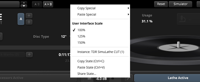
Additional options can be accessed using the standard context menu. This can be opened by Right-clicking on a blank area anywhere in the UI. A click outside of the menu closes it.
Use the “special” context menu commands for copying and pasting all control settings of the Processors Active section or Lathe Active section.
- Copy Special
- Copy Processors State copies the control settings to the clipboard. This allows for applying control settings across different presets, plugin instances, and plugin hosts by using the Paste Processors State command. The control settings can also be applied across SimuLathe CUT and SimuLathe REF.
- Copy Lathe State copies the control settings to the clipboard. This allows for applying control settings across different presets, plugin instances, and plugin hosts by using the Paste Lathe State command. The control settings can also be applied across SimuLathe REF and SimuLathe CUT.
- Paste Special
- Paste Processors State pastes the control settings from the clipboard.
- Paste Lathe State offers pastes the control settings from the clipboard.
Note: Copy/Paste Special is not supported when going from SimuLathe REF to SimuLathe CUT.
User Interface Scale sets the on-screen interface size to a fixed percentage value of 100%, 125%, or 150%.
Instance allows for renaming the specific plug-in instance.
Copy State (Ctrl+C) copies the current control states to the clipboard. This allows for applying control states (i.e. “presets”) across plugin instances and plugin hosts by using the Paste State command.
Paste State (Ctrl+V) pastes the control states from the clipboard.
Tip: Control states (presets) can also be copied from SimuLathe REF to SimuLathe CUT. To copy the control states, select Copy State (Ctrl+C) in SimuLathe REF’s context menu then select Paste State (Ctrl+V) in SimuLathe CUT’s context menu.
Share State opens a dialog with additional preset sharing options via e-mail or internet forums.
Plugin Host Compatibility
Copyright and Acknowledgements
SimuLathe originated as a crazy idea by Helmut Erler, Vladislav Goncharov and Fabien Schivre.
Technical guidance by Helmut Erler. DSP and UI development by Vladislav Goncharov and Fabien Schivre.
Documentation by Shane Johnson
A thousand thanks goes to the fearless disc production experts who helped shape the vision and final product:
- Adam Gonzalves
- Alberto Camerasa (LathesVille)
- Alexander Ott
- Andreas Kauffelt (Schnittstelle)
- Arne Albrecht
- Bob Weston (Chicago Mastering Service)
- Chris Muth
- Diego Ili
- Flo Kaufman (Flokason)
- Frederic Stader
- Greg Reierson (Rare Form Mastering)
- Harvey Jones (Pitchcraft Mastering)
- Jason Goz
- Josh Bonati
- Kamil Kaczmarek
- Michael Lawrence
- Mike Grinser (Man Made Mastering)
- Misjah van der Heiden (24mastering)
- Nene Baratto
- Oihane Contreras Zubillaga (LathesVille)
- Olivia Kolsut
- Paul Gold (Salt Mastering)
- Riccardo Martinelli
- SONO RECORDS
- Sam Berdah
- Steven (My Shank)
- Thorsten Wyk (Optimal-Media)
- Tobias Lill
- Volker Elsässer (Elsässer Galvanics)
Product evaluation and quality control by:
- Ady (Trkmastering)
- Bob Ohlson
- Dax Liniere (Puzzle Factory)
- Eric Recourt
- Gregg Janman
- Ian Steward
- Ilpo Kärkkäinen (Resound)
- Jan Ohlhorst
- Joe Caithness Mastering
- Jonas Ekström (Mastertone)
- Joseph Lyons
- Justin Perkins
- Mario Krušelj
- Miro Pajic
- Murray Campbell (Beatworld)
- Nicholas Di Lorenzo
- Niklas Silen (BManic)
- Nil Hartman
- Rich Prewett
- Roland Löhlbach
- Zvukofor
Copyright © Tokyo Dawn Records. All rights reserved.
All other product and company names are trademarks or registered trademarks of their respective holders.