The Concept
TDR Limiter 6 GE
is a modern dynamics compression and limiting toolkit featuring six specialized
modules that can be arranged in variable order. Together, they cover a
remarkable range of applications from delicate loudness control, to brutal
“brick-walling” and creative mix bus crunching.
Modules
- Dynamics Compressor
- High Frequency Limiter
- Clipper
- Peak Limiter
- Output Protection Limiter
- True Peak and EBU Loudness Meter
Each module offers dedicated control over different types of events, from macro to micro, and allows you to determine the signal path. Combined wisely they can greatly increase the perceived loudness of a mix while preserving superior musical fidelity, punch, and excitement.
With its appealing visual aesthetic, the advanced true peak and EBU R128 compliant loudness metering section gives a detailed insight into the signal’s dynamics. The equal loudness bypass will also make sure the operators’ aural perception isn’t tricked from any loudness differences. A collection of sensible starting points allows for quick, yet precise loudness maximization. If needed, a wide range of options offer endless creative possibilities for getting that optimal setting. Going further, Limiter 6 also enables the operator to build their own personal take on loudness maximization, bus processing, and much more.
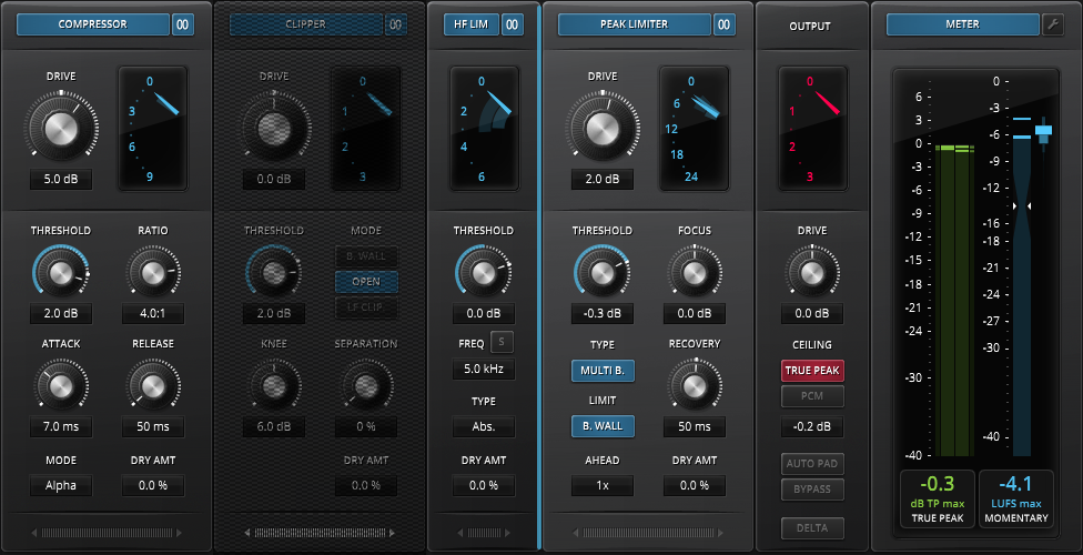
An Overview
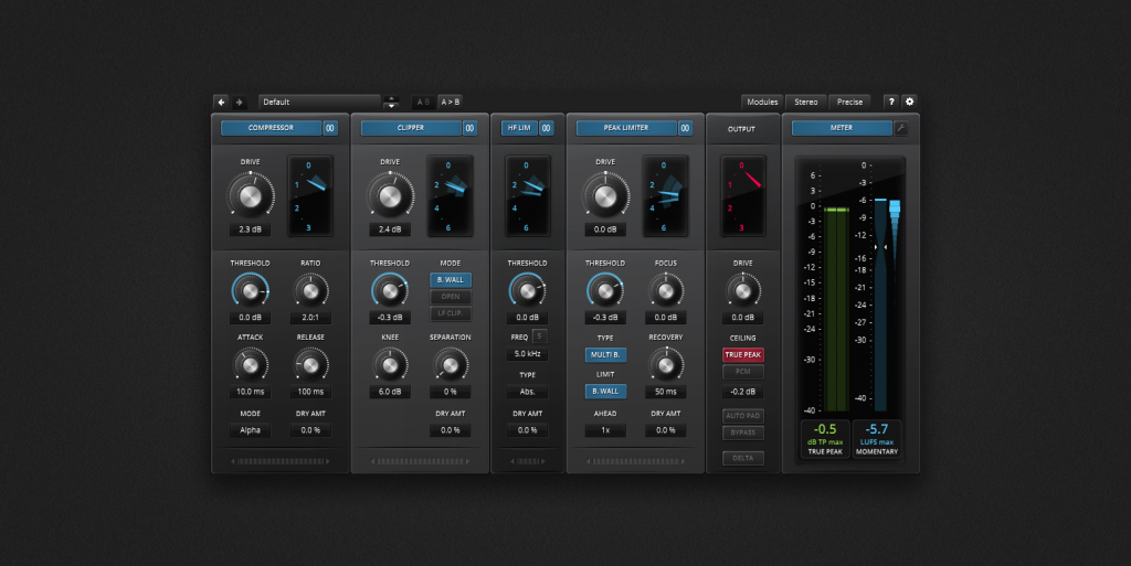
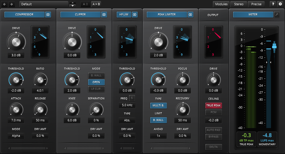
The sheer quantity of Limiter 6’s knobs, buttons and displays can overwhelm even the toughest engineer. In order to develop a sense of orientation, we’ll first take a closer look at the overall module structure.
Limiter 6 follows a simple serial processing structure directly reflected by the visible order of the modules. Audio simply flows left to right.
We have six modules in total, whereby the first four can be reordered to taste. The last two modules, the output module and the meter module, have fixed positions.
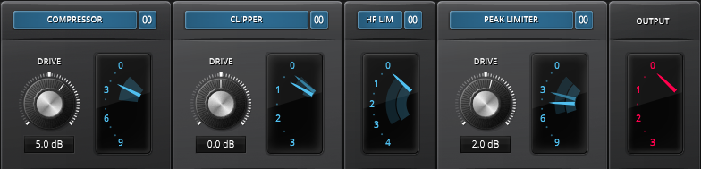
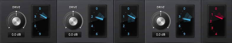
The upper row with big Drive knobs and VU style gain reduction meters contain the most important controls that you’ll need to set up Limiter 6 for new material. On top of each module sits a local bypass button and a stereo/stereo + width switch. The big knobs drive the various modules and push them into gain reduction (see “Gain staging in Limiter 6” below for more details).
The GR (Gain Reduction) meters on the other hand directly inform how far the gain is being pushed down.
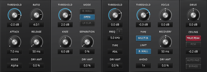
The next row, the “body”, offers detailed access to every module’s behavior. Note that every movable module also features its own Threshold (or Range) control, and a Dry Mix text box.

The bottom row contains the module drag and drop “handles”. Use these to reorder modules to taste.
The output and meter modules are special cases. Their positions are fixed and always last in the processing chain. If needed, the output modules offer a final means of overload protection and equal loudness bypass functionality. The delta button allows for direct previewing of the signal’s pure gain reduction.
Getting Started
It is recommended to first get a full understanding of each module in isolation, then later start experimenting with the combination of modules. Modules can be bypassed and even hidden if required. Only very few cases will really ask for all modules at once, so do not hesitate to turn them off. Minimalism is definitely not the worst habit in audio engineering!
This goes hand in hand with the wide range of features offered by Limiter 6. It is very easy to exaggerate or get distracted.
Make sure to not just simply turn the knobs wildly min to max, but really explore the full range of features in a smooth and delicate manner. There’s plenty to discover.
After getting familiar with all the modules, you should next experiment with their order and get a feel of their interaction.
An obvious strategy would be to order the modules by their speed starting with the compressor, then the peak limiter, and finally the clipper. This would make sure that each module only has to handle the previous module’s overshoots. But this is really just the beginning.
In any possible configuration, the output module’s protection limiter will make sure to get rid of any remaining overloads. This final limiter is meant to protect from any remaining overloads, according to the specified ceiling value.
Though Limiter 6’s factory presets include a collection of inspirational starting points, it’s essentially up to the operator to find the most beneficial combination for any given task.
Note: Right-clicking the preset bar allows for overwriting the default setting or to create persistent user presets.
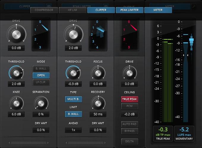
Module Management
Module Order
The four primary processing modules can be reordered to taste. Simply drag the module at the handle and drop it wherever needed (the handle can be found at the bottom of each movable module). Alternatively, clicking either arrow will move the given module one step left or right.
By default (since update 1.2.0), these reordering operations attempt to preserve the previous gain staging balance. This behavior can be bypassed by using Alt-click and drag (Win) or Command-click and drag (Mac) when reordering the modules.
The order of output and meter modules is fixed and can’t be changed.
Module Visibility
| The “Modules” button found in the toolbar opens the “Modules Visibility” menu. This menu allows for showing and hiding each module. The plugin window will resize as needed. |
To show or hide a module, simply click its button in the visibility menu. A click outside of the menu closes it:
Gain Staging in Limiter 6
In order to prevent confusion and redundancy in the user interface, gain staging in Limiter 6 follows a clear principle. Amplification, if existent, is always applied at the input of a module (the HF limiter has no gain control).
This layout has two important consequences:
- Amplification is likely to drive the module’s dynamics processor harder, and to a lesser extent the following modules’ processors.
- There is no module output gain. To make up the gain reduction introduced by a certain module, always use the next available “Drive” knob in the chain.
Further, all DRY MIX/DRY AMT functions are post DRIVE.
Gain Reduction Meters
All modules, except the Meter module, offer their own gain reduction meters.
 | The gain reduction meters will display up to two meter needles depending on their mode, including their mid-term maximum extension. The bright colored meter represents the primary value (Left or combined Stereo channel). The dark colored meter represents the secondary value (Right or Stereo Width channel). Note that the GR meters show the true amount of reduction, not just its theoretical value. This means that the dry mix/dry amount function will be reflected in the meter. Each meter’s range can be changed by clicking the upper or lower half of the meter, using the mouse wheel, or by opening the right-click context menu. |
Module: Compressor
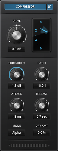 | The compressor module is specifically meant to control the extension of long term dynamic events. Like traditional dynamic compressors, it won’t catch the fastest content but will even out the “body” of the signal improving its presence and density. This is particularly advantageous when operated in combination with other modules. For example, the compressor followed by the clipper will keep the bass and tonal content away from the clipping threshold. As such, only short and slow rising peaks will be affected by the clipper. Interestingly, the clipper followed by the compressor can also lead to useful results. In this instance, subtle clipping and peak flattening of the clipper module will relax the compressor’s job. In particular, it will reduce the compressor’s tendency to overreact to short and sudden peaks, and not recover from them quickly. This is sometimes described as an “overcompression” effect. The most advantageous combination is best found by experimentation. |
Compressor On/Off
This button switches the compressor module on and off. This function can be used to A/B the effect of a module and help save CPU cycles.
Stereo vs Stereo + Width Mode
The small Stereo vs Stereo + Width button switches between linked stereo operation and stereo + width based operation. Holding the Alt key while clicking this button enables fully unlinked stereo operation. This mode should be used with caution, because it has the potential to wildly shift the stereo center around.
Stereo + width is somewhat equivalent to traditional stereo sum and difference processing but with additional controls. These are control over the stereo content, as in the stereo mode, and the stereo width, which is set relative to the stereo control. This makes sure that changes made to a stereo parameter do not affect the stereo width (only the width parameters do).
While this may sound like a needless complication, we think that this setup allows for faster and more intuitive workflows.
Drive
Input gain of the compressor module. Turing this knob clockwise will push the signal against the threshold. As previously mentioned in “Gain staging in Limiter 6”, the compressor’s makeup gain can be set with the next modules’ DRIVE knob.
In Stereo + Width mode, two text sliders are shown instead. The upper controls Drive exactly like the conventional Drive knob. The lower knob, the Width Drive text slider, drives the stereo width level relative to the main Drive parameter. That is, a change of Drive also automatically affects Stereo Width Drive.
Threshold
Threshold defines the level above which the compressor begins to compress the signal. The lower the threshold, the deeper the resulting compression.
In Stereo + Width mode, two text sliders are shown instead. The upper controls the Stereo Threshold exactly like the normal Threshold knob does. The lower knob, the Width Threshold text slider, defines the stereo width level at which the compressor reduces gain (of the width channel).
Ratio
Defines the strength at which the signal will be compressed as it exceeds the threshold.
1:1 represents unity (no compression at all).
2:1 represents a moderate amount of compression, a good starting point.
10:1 represents the maximal amount of compression.
Note that ratio also controls the sharpness of the transfer function “knee”. Low ratios produce very smooth knees, while high ratios approach a sharp, hard “knee”.
Attack
Adjusts the attack speed of gain reduction. Smaller timing values force the compressor to tightly track and compress the audio signal’s dynamics. On the other hand, larger timing values tend to tolerate short overshoots and allow for a more natural, lively compression sound.
Release
Adjusts the release speed of the gain reduction. Sound wise, this parameter essentially controls the density of the outgoing audio signal.
Small release values produce very dense (and loud) results at the cost of increased distortion.
Longer release values better preserve micro dynamics by simply ignoring them. This time, the price is an increase in long term IMD distortion, an effect often called “overcompression”.
Mode
The compressor module offers five different operation modes:
Alpha
A rather clean conventional compressor. It represents a good choice for clean, transparent reduction of the largest signal extension to relax the following stages.
Sigma
The Sigma compressor mode uses a more characterful timing nonlinearity, where timing speeds up with gain reduction. Perfectly suited for creative uses, it can also provoke interesting surprises. During mastering, it’s certainly best used in combination with the DRY MIX function.
Leveler
A levelling algorithm operating with an “idle” window were no dynamic gain reduction takes place. Gain only changes when the signal level crosses the upper or lower limit of the window. This is particularly useful to control the long term dynamic range in a transparent manner. Unlike traditional compressors, this mode doesn’t impose any feel of pressure/tension onto the signal.
Nova
This offers the same compression algorithm found in TDR Nova. It uses soft-knee compression that depends on Ratio. A higher Ratio produces a sharper knee. The internal gain reduction limit also depends on Ratio, which will produce an S-shape compression curve. Its smooth operating 200 Hz, 3 dB/Oct side-chain filter is ideal on the mix bus. Running this module in low latency mode also allows it to be suited for live recording and performing.
Broadcast
3 band compression. The Low to Mid transition uses aggressive 48dB/oct filters, whereby the Mid to High transition relies on transparent 6dB/oct filters. This has the intentional side effect of acting like a phase rotator in the low mids, offering a useful alternative “colour” while also symmetrizing the waveform along the way.
In addition distortion is “shielded” from reaching into the other band, low to mid, and vice versa.
Dry Mix/Dry Amount
DRY MIX adds a portion of the dry signal to the processed signal.
DRY AMOUNT crossfades the dry signal with the processed signal. Modes can be switched by double clicking the DRY MIX or DRY AMOUNT label.
Note that the indicated gain reduction directly depends on the Dry/Wet ratio. For example, a dry wet ratio of 50/50 will reduce the indicated GR by approximately 6dB.
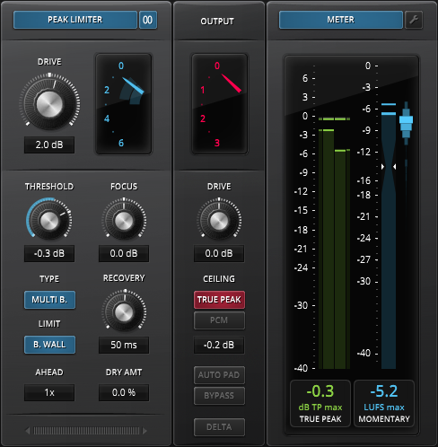
Module: Peak Limiter
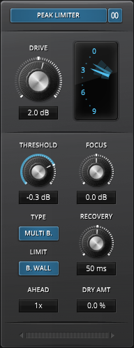 | The peak limiter module is specifically meant to control the extension of mid to short term dynamic events without introducing excessive audible distortion. This is a lookahead, “brick wall” type limiter, so it will reliably prevent most overshoots, while maximizing the perceived loudness of the signal. Two different algorithms are being offered: – An advanced, cross-linked multiband structure essentially combines the advantages of band split limiting (less distortion) with the advantages of wideband limiting (“brick wall” behavior and great density). – A wideband limiter. Each offer its own distinct sound and behavior, as is best explored by ear. The peak limiter shows great strengths in combination with the other modules. Say, with a preceding compressor or HF limiter, or a following clipper. The peak limiter’s “brickwall” can be turned off to creatively leak short transients into following modules. |
Peak Limiter On/Off
This button switches the peak limiter module on and off. This function can be used to A/B the effect of a module and can help save CPU cycles.
Stereo vs Stereo + Width Mode
The small Stereo vs Stereo + Width button switches between linked stereo operation and stereo + width based operation. Holding the Alt key while clicking this button enables fully unlinked stereo operation. This mode should be used with caution, because it has the potential to wildly shift the stereo center around.
Stereo + width is somewhat equivalent to traditional stereo sum and difference processing but with additional controls. These are control over the stereo content, as in the stereo mode, and the stereo width, which is set relative to the stereo control. This makes sure that changes made to a stereo parameter do not affect the stereo width (only the width parameters do).
Drive
Input gain of the peak limiter module. Turning this knob clockwise will push the signal against the threshold, driving it into more limiting.
In Stereo + Width mode, two text sliders are shown instead. The upper controls Drive exactly like the conventional Drive knob. The lower knob, the Width Drive text slider, drives the stereo width level relative to the main Drive parameter. That is, a change of Drive also automatically affects Stereo Width Drive.
Threshold
The peak limiter threshold defines the level above which the limiter will start to control gain. Note that the lookahead detector combined with the limiter’s infinite ratio make threshold effectively an “output ceiling” control.
In Stereo + Width mode, two text sliders are shown instead. The upper controls the Stereo Threshold exactly like the normal Threshold knob does. The lower knob, the Width Threshold text slider, defines the stereo width level at which the peak limiter starts to reduce gain (of the width channel).
Brickwall
The “B. WALL” (brickwall) button turns the internal cross-band linking on and off. This linking is meant to guarantee true brickwall behaviour under most circumstances.
Certain configurations possibly don’t require brickwall behaviour. A following clipper for example, will possibly “find goood use” for the overshoots generated by the non brickwall limiting.
Multi Band
Turns the internal multiband limiting on and off.
Note that this is more than just a crossover with 3 limiters. An elaborate cross-band balancing algorithm guarantees true brickwall behaviour.
Focus
Balances the peak limiter’s frequency dependency. Crudely speaking, positive values prioritize mid frequency transients, while negative value prioritize both low and high frequency transients. This is best explored by ear.
Ahead
Sets the lookahead window size. Limiter 6 uses a small lookahead to anticipate overloads before they happen.
Lookahead is a compromise between low frequency distortion and the preservation of perceived punch and crispiness. Short ahead times are likely to distort the lower registers faster, but generally tend to sound more open and natural. Longer ahead times prevent much more low frequency distortion, but can also impact the integrity of percussive elements.
Recovery
Sets the recovery speed of the limiter’s gain reduction. Short times produce greater sonic density, at the cost of higher distortion. Larger values relax the timing and allow better preserving of the signal’s original micro dynamic structure.
Although similar in nature, this is not a conventional release time. It only partially affects the limiter’s envelope.
Dry Mix/Dry Amount
DRY MIX adds a portion of the dry signal to the processed signal.
DRY AMOUNT crossfades the dry signal with the processed signal. Modes can be switched by double clicking the DRY MIX or DRY AMOUNT label.
Note that the indicated gain reduction directly depends on the Dry/Wet ratio. For example, a dry wet ratio of 50/50 will reduce the indicated GR by approximately 6dB.
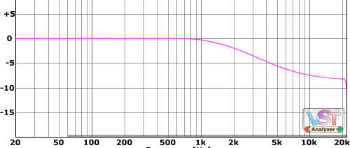
Module: High Frequency Limiter
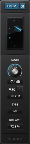 | The High Frequency (HF) Limiter module’s main task is the reduction or compression of excessive high frequency content. This is achieved by splitting the high frequency content, and dynamically subtracting it from the original. Two different types of high frequency control mechanism are available to modulate the high frequency content: An absolute gain dependent mode, or a relative level independent operation mode. |
HF Limiter On/Off
This button switches the high frequency limiter module on and off. This function can be used to A/B the effect of a module and can help save CPU cycles.
Stereo vs Stereo + Width Mode
The small Stereo vs Stereo + Width button switches between standard stereo operation and stereo + width operation.
The latter is somewhat equivalent to traditional stereo sum and difference processing, but with a slight operational difference: Additional controls appear now both offering control over the stereo content (as before in stereo mode) and the stereo width, whereby the width is set relative to the stereo control. This makes sure that changes made to a stereo parameter do not affect the stereo width (only the width parameters do).
Threshold
Adjusts the absolute high frequency threshold. This parameter only appears in absolute mode.
In Stereo + Width mode, two text sliders are shown instead. The upper controls the Stereo Threshold exactly like the normal Threshold knob does. The lower knob, the Width Threshold text slider, defines the stereo width level at which the HF limiter starts to reduce gain (of the width channel).
Range
Adjusts the range of the high frequency reduction in dB. This parameter only appears in relative mode.
In Stereo + Width mode, two text sliders are shown instead. The upper controls the Stereo Range, analoguous to what the normal Range knob does. The lower knob, the Width Range text slider, defines the stereo width dynamic balance at which the HF limiter starts to reduce gain (of the width channel).
Frequency
The corner frequency of the high frequency band (high passed). Under conditions of gain reduction, the HF limiter forms a smooth high shelf filter.
HF Band Solo
Press the “S” button to preview and fine tune the static high frequency band (in some sense, this band represents the HF limiter’s source).
Tip: To preview the effect of the HF limiter’s dynamic gain reduction, use the delta function.
Type
The type of mechanism used to control the extension of high frequency content. Two modes are supported:
Absolute
Reduces high frequency gain as soon as the detected HF band level crosses the threshold. This works well if the material has already been subject to dynamic range compression.
Relative
Reduces high frequency gain relative to the wideband to HF band ratio (i.e. the balance between both). This is particularly useful when processing material having a wide dynamic range.
Dry Mix/Dry Amount
DRY MIX adds a portion of the dry signal to the processed signal.
DRY AMOUNT on the other hand crossfades the dry signal with the processed signal. Modes can be switched by double clicking the DRY MIX or DRY AMOUNT label.
Note that the indicated gain reduction directly depends on the Dry/Wet ratio. For example, a dry wet ratio of 50/50 will reduce the indicated GR by approximately 6dB.
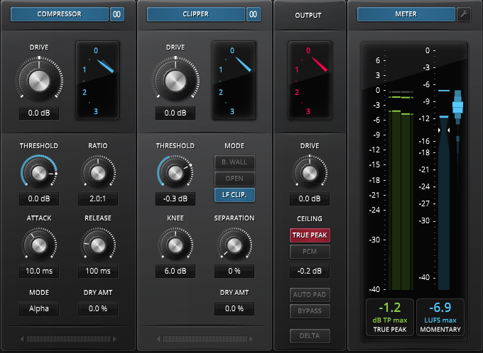
Module: Clipper
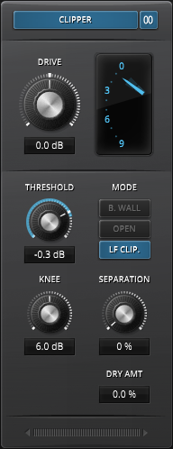 | The clipper module is specifically meant to handle instant/short term dynamic events. The default mode offers a safe brick wall operation. Two further modes relax this strict behavior. Clipper represents the hardest most brutal form of dynamic range compression. When facing complex tonal material, they tend to quickly produce huge amounts of unpleasant distortion. Despite this drawback, clipping also shows unique qualities on certain types of very short, “clicky” material, where it tends to preserve most of the signal’s original impact, punch, and crispiness. Further, they can also act surprisingly well on any inharmonic type of material. The trick is to make sure that the clipper only “sees” material it can handle in a graceful manner. This can be done in various ways, the most obvious ones being a sensible clipping threshold, or the placement of compressor before the clipper. The compressor would optimally have a threshold at least 3-6 dB lower than the clipping threshold. This would make sure that the most critical tonal content gets handled in a rather smooth and clean manner, while all fast and high level events fall under the responsibility of the clipper. |
Clipper On/Off
This button switches the clipper module on and off. This function can be used to A/B the effect of a module and can help save CPU cycles.
Stereo vs Stereo + Width Mode
The small Stereo vs Stereo + Width button switches between standard stereo operation and stereo + width operation.
The latter is somewhat equivalent to traditional stereo sum and difference processing, but with slight operational difference: Additional controls appear now both offering control over the stereo content (as before in stereo mode) and the stereo width, whereby the width is set relative to the stereo control. This makes sure that changes made to a stereo parameter do not affect the stereo width (only the width parameters do).
Drive
Input gain of the clipper module. Turning this knob clockwise will push the signal against the threshold, driving it into more clipping.
In Stereo + Width mode, two text sliders are shown instead. The upper controls Drive exactly like the conventional Drive knob. The lower knob, the Width Drive text slider, drives the stereo width level relative to the main Drive parameter. That is, a change of Drive also automatically affects Stereo Width Drive.
Threshold
The threshold defines the level above which the clipper will start to control gain.
In Stereo + Width mode, two text sliders are shown instead. The upper controls the Stereo Threshold exactly like the normal Threshold knob does. The lower knob, the Width Threshold text slider, defines the stereo width level at which the clipper starts to reduce gain (of the width channel).
Mode
The clipper supports three different operational modes:
B. Wall (Brick wall)
A hard clipper.
Open
A hard clipper having a higher sensitivity toward high frequency content. This generally results in a smoother sound. Most music signals tend to lose level with frequency, hence the open mode makes sure that the clipping effect is more evenly distributed across the spectrum.
LF Clipper
Low frequency specific clipping. This is particularly helpful when trying to control particularly low dynamic frequency content and thus relax the following modules.
Knee
Adjusts the transfer function “knee” of the clipper. 0 dB produces hard knee operation; higher values increase the knee’s smoothness.
Soft, deep knees reducing the order of distortion produced by the clipper, but also introduce drawbacks. Soft knees reach deeper into the signal, so the clipper has to work much more frequently than hard clipping. At the end of the day, they often end up producing more audible side-effects. This is best fine-tuned by ear.
Separation
Adjusts the band separation in percent. This is best imagined as a continuous transition between wideband and multiband clipping control.
Dry Mix/Dry Amount
DRY MIX adds a portion of the dry signal to the processed signal.
DRY AMOUNT crossfades the dry signal with the processed signal. Modes can be switched by double clicking the DRY MIX or DRY AMOUNT label.
Note that the indicated gain reduction directly depends on the Dry/Wet ratio. For example, a dry wet ratio of 50/50 will reduce the indicated GR by approximately 6dB.
Module: Output
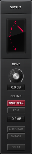 | This output module provides a final means of controlling any remaining overshoots, thus guaranteeing that the output signal level doesn’t exceed the value defined by the output ceiling text-slider. The output limiter has a precise, purely technical function and doesn’t take the listening experience into account. Sustained gain reduction by the output protection limiter will likely restrict the audio fidelity. This limiter is meant to catch occasional overshoots produced by certain module configurations. For best sonic results, the “red” gain reduction should remain as low as possible. Heavy gain reduction is best handled by the Compressor, Peak Limiter and Clipper modules. The ceiling can be defined in two manners. The PCM Ceiling purely limits the PCM sample values, without considering the amplitude of the true, continuous waveform. This mode potentially provokes relatively strong aliasing and so called “inter-sample peaks”. The True Peak ceiling on the other hand limits an approximation (very safe and accurate) of the true waveform. This both limits the True peak by limited amounts, and also the PCM output level. |
Limiter 6 GE also offers an equal loudness bypass workflow. Unlike most other TDR plugin’s equal loudness bypass cases, limiting would require far too strong bypass levels. Given this restriction, the equal loudness bypass function will only appear after activating the Auto Pad, which statically pads the output level for safe (clipping free) equal loudness bypass operation.
The Delta function allows previewing the accumulated effect of all dynamic gain reductions that the signal is being subject too. This is a reliable way to spotting and fixing distortion and artifacts. This module can neither be moved nor hidden; it always remains the last processing module in the chain.
Drive
Drives the final output limiter. It is recommended to use the protection limiter in a conservative manner and keep the gain reduction rather low.
Ceiling
Defines the maximal peak level to be tolerated by the output protection limiter. It can be specified in two manners, either by PCM level (level of the provided samples) or True Peak level (level of the reconstructed, continuous waveform). Press either button to select the mode, or disable the protection limiter. In the latter case, a LED will appear and flash up when the output PCM signal overshoots 0 dB.
Note that the PCM and True Peak ceilings are two independent parameters that can hold different ceilings (but only one of them can be active). Further, the PCM and True Peak ceilings can also directly control the peak meter’s clipping thresholds.
Auto Pad
Smoothly reduces the output level to allow a clipping free equal loudness bypass comparison. As soon this function is activated, the Bypass button will turn into the Equal Loudness Bypass button.
Note that the peak and loudness meters do not reflect the pad. Instead, a small text box will appear above the meter module to indicate a padded output.
Bypass
Bypasses all modules. Limiter 6 then simply routes the input to the output. The bypass function is click free and latency compensated.
Equal Loudness Bypass
Engages a loudness compensated bypass. When engaged, the bypass signal is gain compensated to match the processor’s output loudness. This gain compensation is static, and thus doesn’t introduce any form of distortion.
Note that the Equal Loudness Bypass only appears once Auto Pad is active.
Delta
Allows previewing the dynamic gain reduction that is being removed from the original signal. Gain differences between modules are ignored in this process.
The delta function is a great way to track down distortions and get them under control.
Module: Meter
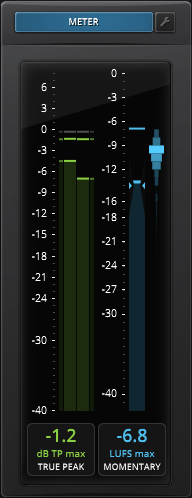 | The meter module offers a full featured EBU R128 compliant peak meter and loudness meter. Analogous to the output module’s ceiling parameter, the peak meter can operate in PCM mode and true peak mode. The former purely tracks the original samples, while the latter precisely approximates the original continuous signal that the PCM samples are representing. The loudness meter returns an approximation of the perceived loudness, as defined by the EBU R-128 standard. All ranges, scales and offsets can be configured to taste. This module can be hidden if needed, but will always remain last in the chain. Obviously, it always measures the output signal. |
Peak Meter
Measures the peak level of the incoming signal and indicates both their momentary and maximum values. Two operational modes are simultaneously supported:
– The PCM levels are shown via the narrow outer bars, for the left and right channels accordingly. Their maximum values are shown in the form of small markers.
– The true peak levels are shown via the wide inner bars, for the left and right channels accordingly.
As soon either value overshoots its ceiling value (as defined by the output module’s ceiling parameter), the marker color will turn red. Clicking the meter area will reset all buffers (i.e. all maxima).
The meter range can be adapted as needed by clicking the upper or lower half of the scale, using the mouse wheel, or selecting the appropriate range via the context menu.
 | The value box found below the meter returns a single value in textual form. Four different modes can be selected via click, mouse wheel, or context menu: PCM, PCM max, True Peak and True Peak max. |
Note that this mode is also linked to the output module’s ceiling mode, so that any change of the output ceiling modes will automatically change the meter’s indicated peak mode (whenever it makes sense).
Loudness Meter
Measures the loudness of the incoming signal in compliance with the EBU R128 recommendation. This popular broadcast metering standard involves three different operational modes:
Momentary
A rather fast RMS measure giving a good idea of short term loudness. This mode is a rather simple, short term, K-weighted, RMS value well suited for music production.
In addition, a loudness histogram gives a good idea of the loudness distribution. This might indicate a need for compression, or simply help when comparing two different tracks. Looks cool, too
Short Term
A moderately fast, gated RMS measure giving a good idea of medium term loudness. This mode is particularly useful for dialogue.
A bar representing the EBU loudness range (LRA) is shown on the right hand side of the loudness meter.
Integrated
A slow gated RMS measure representing the long term loudness of a potentially wide dynamic range program. This is best suited for very long duration music content, such as DJ Mixes, radio, podcasts and similar.
A bar representing the EBU loudness range (LRA) is shown on the right hand side of the loudness meter.
 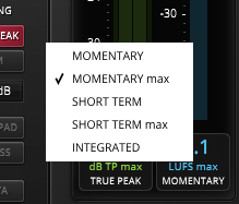 | These modes can be selected via clicking on the loudness value box, using the mouse wheel, or by the context menu. The Momentary and Short Term loudness bar include max hold markers, which can also be chosen as source for the value box. |
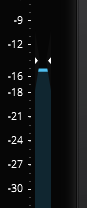 | EBU loudness reference is indicated via the two triangles forming a “bottleneck” for the loudness bar. In relative EBU Scale mode, this is the level that defines the 0 LU point. You can set the reference level either via the meter configuration view (see below), or by holding Alt + left clicking the value box. The latter will simply take the indicated loudness value and set it as loudness reference. |
The meter scale can be changed by left clicking the upper or lower halves of the scale, via the mouse wheel, or with help of the context menu. Note that the two officially recommended ranges, EBU-9 and EBU-18, are only accessible via the context menu; they are not part of the left click/mouse wheel cycle, for esthetic reasons.
Meter Configuration
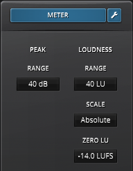 | Click the small “wrench” button to open the meter configuration view. The Range sliders control the peak and loudness ranges. The Scale slider controls the EBU scale mode. EBU R128 offers two different types of scales: An Absolute scale delivering a LUFS value (loudness unit full scale). A Relative scale delivering a LU value relative to the Zero LU point. Zero LU represents the EBU loudness reference level. |
Alternatively, the Zero LU point can be set by holding the Alt key and clicking the loudness value box. The Zero LU point will then become equal to the currently measured LUFS value.
Toolbar
Undo/Redo
| Use the undo/redo buttons to navigate previous control states. The exact event is shown in a tooltip. Note that certain controls are not tracked by this function (e.g. “Bypass”), as that would not make much sense. |
Preset Management
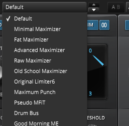 | The preset drop-down list offers quick access to factory settings and user presets. Alternatively, the up/down buttons allow you to cycle through the presets. |
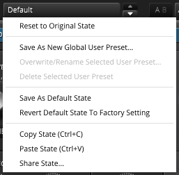 | Advanced preset management options are available from the context menu (right-click). Reset to Original state resets the currently active preset to its original state. Save As New Global User Preset opens a dialog used to create User Presets. Note that these presets persist across sessions and DAWs (presets are saved on your machine). The total amount of user presets is limited to 20. Copy and Paste allow copying control states (i.e. “presets”) across plugin instances and plugin hosts. Additionally, Share State opens a dialog with additional preset sharing options via e-mail or internet forums. These three options are available in the standard context menu as well. |
A/B Control
| A/B allows comparison of two alternative control settings. A>B and B<A copies one state over the other. |
Modules
| The “Modules” button found in the toolbar opens the “Modules Visibility” menu. This menu allows for showing and hiding each module. The plugin window will resize as needed. |
Mono/Stereo
 | The audio input can be processed in stereo or a forced mono mode. Use the latter if your material is mono and the DAW doesn’t support true mono channels. |
Processing Quality
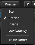 | Limiter 6 offers four different quality modes: · Eco: Economic mode · Precise: Default quality · Insane: Very high quality · Low Latency: A low latency mode. Note that this feature has been intentionally designed to be non-creative. The different quality modes purely result in different inter-sample accuracy and amount of aliasing by-products (i.e. the higher the quality mode, the less likely negative or unnatural side-effects will appear). In addition, a flat, 16 bit TPDF (triangular probability) dither can be turned on or off as needed. |
Help Mode
| The dynamic help mode offers detailed information about the various elements of the user interface. Click “?” to activate the online help and move the mouse cursor over the control of interest. A small info bubble will appear. Another left- click closes the help mode. |
Settings
| The settings button opens a dialog which gives control over additional plugin options. |
Slider allows for changing the behavior of knobs and control points in response to the mouse. Under Continuous Drag,knob and controller movement relies on mouse speed when Velocity is enabled. When Linear is enabled, knob and controller movement is proportional to mouse movement. Drag Sensitivity sets the linear sensitivity of the knob and controller movement further.
Plug-in controls, knobs, and control points can be adjusted using Left-click & drag (Continuous) and Right-click & drag (Stepped) by default. Mouse Configuration swaps the Continuous and Stepped behaviors between the left and right mouse buttons when selecting Invert Left/Right Buttons. Note that the default stepped values can be customized via the product configuration file. See “Local data” below for instructions on how to access this file.
Graphics allows for changing the interface size and its rendering behavior. User Interface Scale sets the on-screen interface size to a fixed percentage value. Draw Mode enables Software or OpenGL (experimental) graphics rendering. Note that graphics performance can improve on some systems using OpenGL based rendering, but is generally less compatible.
Processing shows the plug-in latency and sample rate details. Highest quality rendering enables the option to always render at the highest Processing Quality, no matter what type is enabled in the Toolbar. See the “Processing Quality” subchapter for more details on these modes.
Registration offers access to offline and online product registration options. See the “Product Registration” chapter for more information.
Local Data allows for exporting and importing user preferences, presets, and keys, to and from other systems. Local data can also be deleted for all Tokyo Dawn Labs plug-ins using the Trash Can button.
In addition, the Folder button opens the Tokyo Dawn Labs local data folder containing all configuration files and keys. Note that these operations affect all TDR plug-ins, and not just TDR Limiter 6 GE.
Updates allows to Check for updates and to Download latest version. Automatic Lookups can be enabled to Check for updates (once per day).
Help contains Documentation and Support links for the user manual, official video tutorial, report a bug, and support.
About shows the version number, build date, format, credits, and other detailed information.
Context Menu
Standard Context Menu
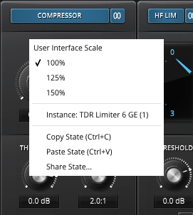 | Additional options can be accessed using the standard context menu. This can be opened by right-clicking on a blank area anywhere in the UI. A click outside of the menu closes it. User Interface Scale sets the on-screen interface size to a fixed percentage value of 100%, 125%, or 150%. Instance allows for renaming the specific plug-in instance. Copy State (Ctrl+C) and Paste State (Ctrl+V) allows copying control states (i.e. “presets”) across plugin instances and plugin hosts. Share State opens a dialog with additional preset sharing options via e-mail or internet forums. |