The Concept

TDR Kotelnikov GE is a wideband dynamics processor combining high fidelity dynamic range control with deep musical flexibility. As a descendant of the venerable TDR Feedback Compressor product family, Kotelnikov GE has directly inherited several unique features such as a proven control scheme, individual release control for peak and RMS content, an intuitive user interface, and powerful, state of the art, high-precision algorithms.
With a sonic signature best described as “stealthy”, Kotelnikov GE has the ability to manipulate the dynamic range by dramatic amounts, while carefully preserving the original tone, timbre and punch of a musical signal. As such, it is perfectly suited to stereo bus compression as well as other critical applications.
Kotelnikov GE does not try to emulate any previously available device. The concept is a proud digital processor, it is the original!
Notable features
- 64bit floating point precision for all relevant calculations
- Multi-rate processing structure for highest accuracy
- “Delta” oversampled signal path (bit transparent at 0dB gain reduction)
- Super fast, yet natural sounding compression
- Control scheme based on “Crest factor”, offering independent release controls for peak and RMS events
- Flexible sidechain highpass filter
- Advanced stereo linking options optimized for the stereo bus
- Delta preview mode to preview the difference between compressed and original signal
- Latency compensated parallel bypass (i.e. processing not interrupted)
- Extensive documentation
Precision, Aliasing and the Solution
Controlling the dynamic range of an audio signal in the digital domain is not as easy as it looks. A whole array of problems makes it very difficult to build a truly effective and musically attractive compressor in the digital domain.
The most significant restrictions are due to the discrete (i.e. “stepped”) nature of digital signal storage. Without delving too deep into the mathematics, it is essential to understand that the data stored in audio-files is not the actual analogue audio signal. It is a very economic, intermediate format. The true analogue signal is only reconstructed by the anti-alias filter inside the D/A converter. However, if one wants to control the amplitude of music accurately, it is absolutely essential to know the actual waveform (i.e. it needs to know about the values between samples as well).
Another huge problem in digital dynamics control is a phenomenon called aliasing or Moiré images. Aliasing appears in all discrete (i.e. “digital”) systems as soon the frequency of a signal exceeds the Nyquist rate (half the sample-rate). The evil detail here is that contrary to analogue systems, signals exceeding the bandwidth aren’t gradually “faded out”, instead, they mirror at the Nyquist frequency and overlap into the audible range at full energy, and in this process, lose any harmonic relation to the original signal.
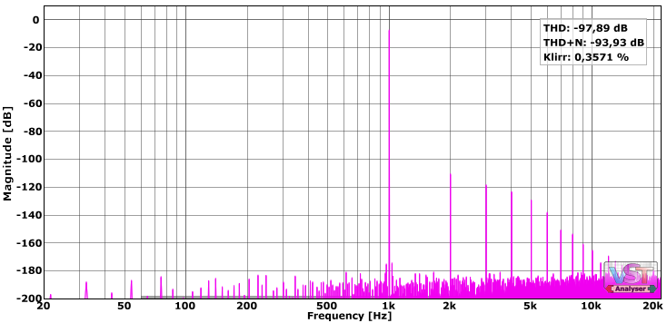
Compressors are non-linear systems. All non-linear systems add harmonic (or non-harmonic) content to the processed signal and thus have the potential to extend the bandwidth significantly. The more aggressive the non-linearity, the stronger and higher the newly generated partials (harmonics). If the sample-rate is too low to handle the extended bandwidth, these harmonics will alias and lose their harmonic relation to the fundamental, resulting in inaccurate, “unwanted” behavior, which in turn directly produces an unpleasant sound.
Kotelnikov GE’s algorithm was carefully designed to avoid these issues. To achieve this in an efficient manner, the algorithm is split in two parts, both typically running at higher rates than the original signal (given a standard rate such as 44.1kHz or 48kHz).
- Sidechain
The sidechain is responsible for generating a control signal for the gain cell. It consists of several non-linear elements such as the threshold, RMS detection and timing filters. To avoid aliasing in the control signal (which would severely limit the accuracy of the compression), the sidechain uses a bandwidth up to 20x wider than the audible bandwidth. - Gain Cell
The gain cell is a central part of the compressor where the audio signal’s level is adjusted by the control signal delivered by the sidechain. This operation is a non-linear process and potentially doubles the bandwidth. To handle this bandwidth, this multiplication always runs at a minimum of double the audio sample rate (i.e. at least 88.2kHz). One interesting design feature of Kotelnikov GE is that only the compressed portion of the signal (listen via “Delta” switch) is oversampled. This leaves the original signal completely untouched – as long as no gain reduction is occurring, the plugin is 100% bit transparent.
In both cases, the resampling is done with very high quality linear-phase time-domain convolution.
Please note that these quality improvements come at a price – CPU cycles – but from a sonic point of view, and in the context of the fast growth of computer power, we think they are well worth the compromise.
Audio Dynamics Control
Beside the more or less obvious technical issues illustrated in the previous chapter, generations of audio engineers suffered from the fact that the dynamic behavior of music signals can be very complex. Controlling these dynamics, be it overload protection, loudness balancing or creative shaping is hard to achieve without introducing negative side-effects (audible collateral damage). The central problem being the processor’s unawareness of musical criteria, which in turn enforces its own sound (and intellectual restrictions) onto the signal.
In the best case, this common phenomenon is referred to as a compressor’s “color” and sometimes can be of great creative use. However, it also means that the processor alters the original fidelity in one way or another. There are times when the audio engineer faces a dynamic challenge, an error that needs correction, but doesn’t want to accept any additional color being brushed all over the entire signal. This is particularly important to the mastering engineer, especially in the case of high quality mixes, but also during creative shaping of natural instruments in a mix.
Most offers on the market are based on rather crude attack/release timing concepts, sometimes combined with more or less intelligent automatisms. In fact, they aren’t much more elaborate than simple thermostats. However, dynamics in music usually do not only consist of attack and decay phases, they are far more complicated. In order to control dynamics in a both effective and transparent manner, it is essential that the processor has the ability to analyze the signal in a musically sensible manner. It’s no wonder that dynamics control systems purely based on A/R models are much better suited to relatively simple signals such as monophonic instruments or other sources already having predictable dynamics, and typically do more harm than good once they face more complex material and/or processing tasks.
Kotelnikov GE uses an elaborate control system based on two specialized parallel paths, each handling specific signal phases independently with high technical effectivity and musical grace. The compressor runs two distinct and separate detection and compression algorithms in parallel:
- Peak Path
The peak detection/compression path primarily follows the rectified version of the (true!) audio waveform with great precision. The peak path’s release phase can be tuned via the PEAK RELEASE control, but also automatically accelerates the release time in certain, high dynamic range situations. This avoids over-compression of small, “crispy” transient events. This form of over-compression is highly audible, as it dulls the original signal substantially and can creates a “nervous” pumping side-effect.
- RMS Path
The RMS path reacts to overall energy levels (similar to human hearing) and ignores short transients. It can be seen as a very slow and smooth compressor that handles the constant or ‘steady-state’ parts of the signal. To be honest, Kotelnikov GE’s RMS path doesn’t use a true RMS detection in the “text-book” sense. Instead, it relies on a highly advanced derivate of the regular RMS detector based on a precise Hilbert Transform detector. The result is a frequency-independent RMS detector, practically free of any harmonic distortion. Contrary to conventional RMS detectors which handle low frequencies much like peak detectors and only higher frequencies as true RMS, Kotelnikov GE’s RMS stage automatically uses the optimal RMS window size for every frequency. Additionally, Kotelnikov GE’s RMS path features an advanced release gating (“freezing”) mechanism preventing noise floor build-ups during programme pauses as well as other forms of pumping. It activates as soon the RMS section detects a sudden pause in the input signal.
To summarize, in contrast to the peak stage, the RMS stage’s own dynamic behavior has the ability to lengthen the RMS release time as required by given audio content. Kotelnikov GE can even increase RMS release to (almost) infinity during certain situations.
The section generating the highest reduction at a specific point in time takes control of the whole compression action. Technically speaking, we have 2 cross-linked side-chains running in parallel, whereby the peak section mostly controls short, high amplitude events and the RMS section takes control over sections having “steady state dynamics”. This contradiction is perhaps better explained as “Sections without substantial dynamics”.
This unique approach offers all of the advantages of peak compression combined with all of the advantages of RMS compression. Furthermore, the RMS path negates the disadvantages of the peak path and vice versa. This design guarantees a very stable stereo image and low compression artifacts over a wide range of material and settings.
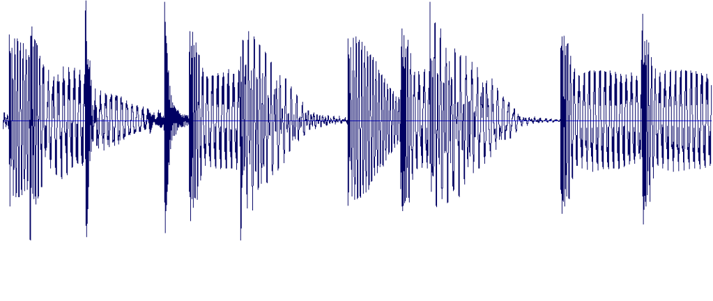
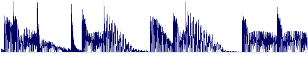
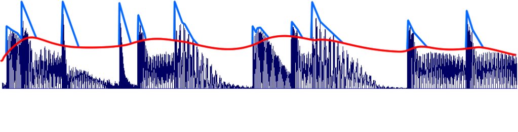
The examples below roughly illustrate the general idea:
Input AC
Input DC (Absolute Input)
Peak Section
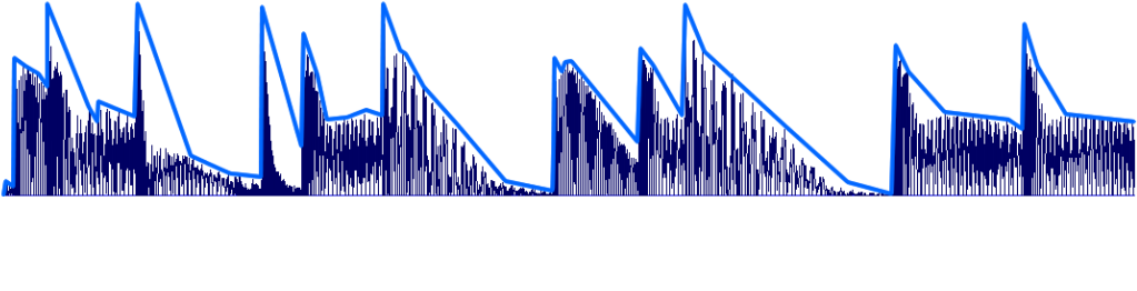
RMS Section
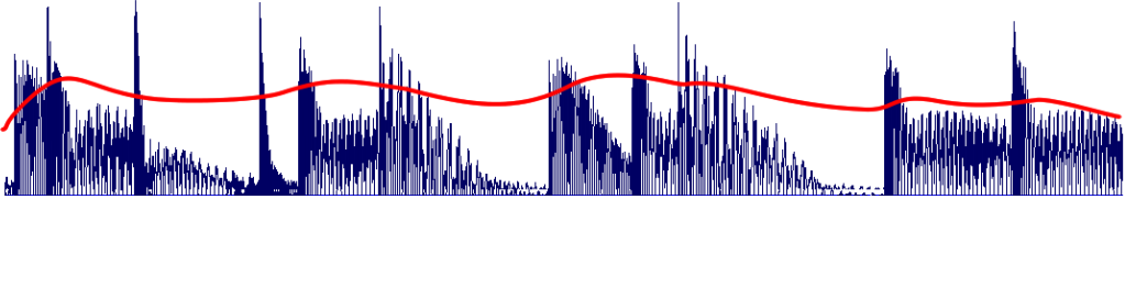
Peak + RMS Combined
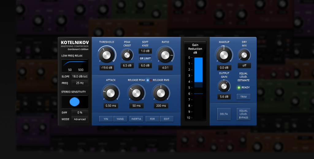
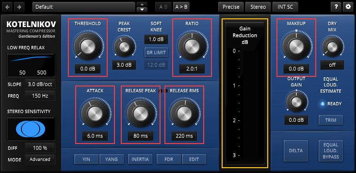
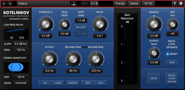
Controls and Displays
Kotelnikov GE offers deep access to various musically relevant parameters. Most of them will be familiar to the experienced audio engineer. A few less common parameters however, deserve special attention. The following section addresses the purpose, meaning and internal mechanisms of the user-interface.
In order to improve UI navigation, the user interface is structured in logical sections:
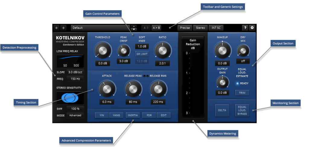
- Gain Control Parameters
- Toolbar and Generic Settings
- Output Section
- Monitoring Section
- Dynamics Metering
- Advanced Compression Parameters
- Timing Section
- Detection Preprocessing
Detection Pre-processing
Low Frequency Relaxation
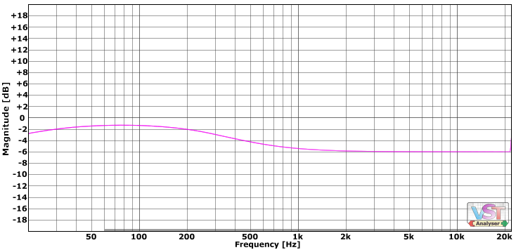
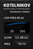 | LOW FREQ RELAX (low frequency relaxation) consists of a specialized high pass filter purely meant to control (i.e. correct*) the compressor’s sensitivity to low frequency content. Or from a different perspective, it allows to make the compressor’s threshold frequency dependent. The filter’s corner FREQUENCY ranges from 25Hz to 500Hz and offers 4 different filter SLOPE options: 0dB/Oct (filter “off”), 3dB/Oct, 6dB/Oct and 12dB/Oct. *The spectral distribution of typical music content and speech is not linear. Instead, it has the tendency to approximate a pink noise distribution (pink noise has a slope falling 3dB per octave). Given this fact, and without additional weighting, a wide-band compressor will somewhat over-react to low frequency content and accordingly under-react to high frequency content. This central problem has the potential to introduce negative side-effects such as pumping and distortion, as well as a severe reduction of the impact and neutrality of compression. Use the LOW FREQUENCY RELAX filter to correct this behavior. Given typical music content, a 3dB/Oct slope represents the theoretically most reasonable compromise for preservation of the original frequency balance. Stronger slopes will typically emphasize low frequency events[DL1] , more shallow slopes tend to reduce their impact (and potentially provoke audible side-effects). |
Stereo Sensitivity
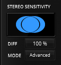 | STEREO SENSITIVITY defines how the compressor reacts to stereo content. Technically speaking, it controls how the detection links both channels. Note that Kotelnikov GE is never allowed to change gain of the L and R channels independently (“dual mono”), as this would directly result in an uncontrollable blurring of the stereo image, and the stereo center in particular would start to move around erratically. 0% DIFF (stereo difference) means that the compressor completely ignores “anti-phase” content, or in other words, the compressor is allowed to dynamically boost difference content (stereo “width”), if existent. This is equivalent to a “sum link”. 100% DIFF tells the compressor to follow the channel having the highest amplitude. This mode has the advantage of being able to preserve the original stereo position and width, and of offering effective overload protection. However, the downside are potential stereo cross-modulation products (which is to say, left channel produces distortion in the right channel). The best results are typically achieved somewhere between these two extremes. MODE switches between “Basic”, a legacy stereo linking mode, and the new “Advanced” linking mode. They differ only in details and both are offered for compatibility reasons. The “Advanced” mode shows greater fidelity in complex stereo situations and is even lighter on the CPU. Please note that the DIFF control will lose its effect over the RMS path in this mode. |
Gain Control
Threshold
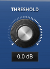 | THRESHOLD defines the RMS level above which the compressor begins to compress the signal. The lower the threshold, the deeper the “grab” and the more compression. Keep in mind that the RMS level of a typical music signal is much lower than the peak level, sometimes up to 10dB or more in the case of very dry drums and percussions. In the case of a sine-wave, the RMS value will be about 3dB lower than the detected peak value. The more dynamic the signal is, the lower the detected RMS level will be. |
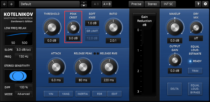
Peak Crest
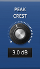 | PEAK CREST adjusts the threshold of the peak path relative to the main (RMS) Threshold. A Peak Crest of zero sets both paths to equal thresholds, a positive Peak Crest increases the threshold of the peak path in order to compress fast events (transients) only for higher levels. A negative peak-crest on the other hand reduces the peak stage’s threshold even further, which in turn results in a very aggressive compression sound. Be aware that the peak level and RMS level can differ greatly depending on the material. A sinewave input of 0dBFS for example has a peak level of approximately 0dB and an RMS level of approximately -3dB. However, it is generally recommend to tune peak-crest in such a manner that a sine wave always triggers slightly more RMS compression than peak compression. Increase the peak above 3dB to guarantee virtually distortion free handling of tonal content. Kotelnikov GE reaches its optimal state with peak crest settings between 3dB and 8dB, depending on the material. Higher peak crest values increase the smoothness of compression, lower values result in more aggressive compression. Turning PEAK CREST full left disables the RMS sections completely. Full right disables the Peak section. |
Soft Knee
 | SOFT KNEE adjusts the threshold transition “softness”. Small knee values create a sharp transition at the threshold point, while higher knee values will compress more gradually, but also reduce the effective threshold (the “knee” extends below threshold). |
GR Limit
 | GR LIMIT (gain reduction limit), restricts the maximum amount of gain reduction to the specified value when enabled. This option results in an “S-shaped” transfer function which stops the dynamic compression at extreme GR values. The sharpness of this limit is defined by the SOFT KNEE control. The larger the knee, the more gradual the GR will be limited. |
Ratio
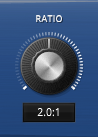 | RATIO defines the strength at which the signal will be compressed as it exceeds the threshold. The range is fully continuous between 1.1:1 and 7:1. Note that the FDR function offers additional means of shaping ratio in a frequency dependent manner. |
Timing Section
Attack
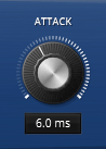 | The ATTACK time controls how long the compressor takes to reach full gain reduction. Fast attack times respond quickly to level changes in the sidechain. Slow attack times on the other hand respond more slowly and smoothly, letting short events (transients) pass through the compressor without much gain reduction. Note that the indicated value is just a rough reference point. To be accurate, it specifies the attack time of the peak path. The attack time for RMS content is substantially slower than the indicated value. The effective attack time greatly depends on the signal’s characteristics and peak crest setting. Kotelnikov GE offers particularly fast reaction times, much smaller than a single sample. Attack times that are too fast can easily distort low frequency content, so be careful with its use. |
Release LEDs
| Kotelnikov GE dynamically chooses the most suitable “release path” depending on the program material. Two virtual LEDs indicate the currently active release path. |
Release Peak
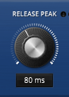 | RELEASE PEAK defines how quickly gain recovers after short overloads (i.e. fast transients). Note that the release peak section automatically accelerates release time substantially in cases of high dynamic range content such as drum, percussion or similar “clicky” material. This behavior prevents the over-compression typically appearing after short dynamic events. The value specified by the user only describes the average case. The release section’s automatism speeds up release where suitable. As always, and with every parameter, tune this by ear. |
Release RMS
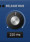 | RELEASE RMS defines how fast gain recovers after sustained gain reduction. Similarly to the peak sections, the effective RMS release is subject to several elaborate automatisms. The true RMS release depends on signal frequency and dynamics. Kotelnikov GE’s RMS stage automatically slows down release where applicable and in rare situations even up to almost infinity. |
More on the Timing Section
Dual release paths offer a wide range of musically useful options. For example; single drum peaks can be allowed to recover quickly to avoid “dulling” and “breathing” side-effects. At the same time, sustained content like bass-lines or synth pads can recover more slowly and thus strongly reduce typical side-effects like “pumping” and distortion.
For complex material such as full mixes we recommend a RELEASE PEAK value between 25-100ms and RELEASE RMS values above 150ms. Faster settings are useful for particularly dynamic material like solo drums, percussion and acapellas. Use PEAK CREST to control the overall aggressiveness of the process.
Input characteristics and the selected PEAK CREST setting have a substantial effect on the internal peak/RMS release path switching.
Because the peak path is much more sensitive than the RMS path, setting the RELEASE PEAK to a higher value than RELEASE RMS while keeping the PEAK CREST low effectively disables the RMS part of the compressor.
Advanced Compressor Parameters
Yin/Yang
| Yin and Yang change the type of harmonics generated during compression. Normally, a precise compressor algorithm generates purely odd-order partials. These YIN/YANG options change the timbre naturally generated by the gain detection and reduction mechanisms, but without affecting the overall precision and values of the various parameters. Yin and Yang allow the compressor to generate even-ordered partials as well, whereby YIN affects the low & low-mid content and YANG the mid & high frequency content. The strength of the effect directly depends on the aggressiveness of compression. This means that the sonic impact can be very subtle, with slow compression settings in particular. Note that YIN and YANG’s effects are set up to cancel each other out over the vocal frequency range, that is, activating both YIN and YANG does not create more harmonics than only pressing, say, YIN. |
Inertia
| The INERTIA function affects timing in a gain reduction dependent manner. The compressor will slow down at low amounts of gain reduction and speed up at high amounts. In addition, the gain reduction smoothly hits the breaks as it approaches ~16dB. This behaviour is a typical feature of optically controlled compressors. Unlike the originals however, INERTIA also covers Kotelnikov GE’s wide timing parameter ranges. |
-Inertia (Inverted)
| Holding the Alt key while pressing INERTIA activates the -INERTIA mode (inverted INERTIA). This mode has been specifically developed to support an exotic upward compression technique. It uses gain reduction limiting in combination with deep thresholds to achieve a boost of low/mid level events while ignoring events having the high levels. As with the default INERTIA mode, two mechanisms come into play: Release speed slows down with gain reduction (and thus, speeds up at low amounts of gain reduction) and the maximal amount of gain reduction becomes strongly limited. The exact amount of maximal gain reduction depends on RATIO. |
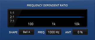
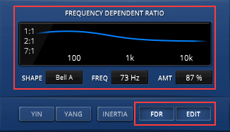
Frequency Dependent Ratio
| Kotelnikov GE allows for controlling the ratio as a function of frequency. In other words, it offers access to FREQUENCY DEPENDENT RATIO (FDR). Although somewhat similar to side-chain filtering, the sonic effect is different and offers an additional degree of freedom to the passionate gain rider! J FDR basically acts like a dynamic EQ. An important detail about FDR is that the audible effect grows with gain reduction. Click FDR to activate/disable the frequency dependent ratio. Click EDIT to activate the FDR detail view. This display plots ratio against frequency. The lower the line, the higher the ratio at that specific frequency. Note that FDR is only able to reduce the value specified via RATIO the knob. |
SHAPE offers 5 different options:
- Shelf A: A wide shelf
- Shelf B: A steep shelf
- Bell A: A wide bell
- Bell B: A narrow bell
- EL Curve: A curve following the equal loudness contours as a function of playback level.
FREQ defines the center/cutoff frequency of the selected shape (inactive for the EL Curve option).
AMT controls the amount of “ratio” being reduced at the frequency (region) of interest. The parameter ranges from -100% over 0% (no change) to 100%.
Output Section
A Note on Auto Gain
Several attempts have been made to solve the problem of auto-gain in compressors.. Most of them rely on rather simplistic approaches. These types of threshold/ratio based auto-gain calculations typically ignore implications given by the timing parameters. This leads to severe mismatches between the estimated auto-gain and the truly required make-up gain. We think that such approaches create more problems than they solve.
However, another closely related problem is equal loudness monitoring, which is seen as essential for an audio engineer to be able qualify a compressor’s action. A higher loudness of only 1dB usually seems to sound better, even if it contains weird saturation or pumping).
Kotelnikov GE uses an elaborate equal loudness detection system which supports two separate equal loudness oriented workflows:
- Equal loudness trim button (semi-automatic, explicit)
Semi-automatic trimming of output gain according to in/out loudness difference. - Equal loudness bypass (automatic, implicit)
Automatic adjustment of the bypass signal according to in/out loudness difference, whereby loudness estimation freezes during active bypass state.
We found these two workflows to be the least obtrusive and most effective solution without restricting more traditional manual makeup gain workflows. The equal loudness detection system needs some time to analyze the current situation which is indicated by the EQUAL LOUDNESS LED. (See below for more details.)
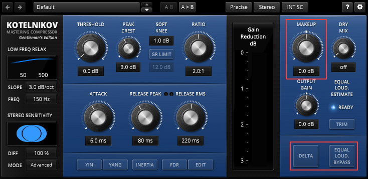
Makeup
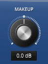 | MAKEUP is meant to compensate the gain reduction introduced by the compressor. The makeup control can also attenuate the compressed signal by up to 60dB which is useful for parallel compression techniques (e.g. by setting DRY MIX to 0 dB and using MAKEUP to add subtle amounts of compression). |
Dry Mix
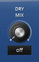 | Dry Mix blends the original signal into the processed (i.e. compressed) part. It enables the use of parallel compression techniques (upward compression, “NY compression”) without complicated routings or DAW latency compensation issues. Dry Mix and Make-up Gain form a 2 channel mixer. Double clicking the DRY MIX label switches the mechanism into a traditional DRY / WET mode. |
Output Gain
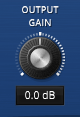 | Output Gain controls the compressor’s output gain without affecting the balance between compressed and dry mix signals. |
Equal Loudness Trim
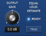 | Pressing the TRIM button automatically adapts OUTPUT GAIN to in order to match the estimated input loudness with the output loudness. Roll the mouse over the TRIM button to show the target output gain. Note that the accuracy of the internal equal loudness calculation directly depends on the current estimation state, as indicated by the EQUAL LOUDNESS ESTIMATION LED. Before pressing TRIM, make sure the LED is either showing a green (“ready”) or blue (“equal”) color. |
Equal Loudness Estimation LED
 | The EQUAL LOUDNESS ESTIMATION LED indicates the current quality (or error) of the internal equal loudness calculation. The process needs some time to settle, and can be disturbed as soon as either control parameters or signal content changes dramatically. In this case the LED will flash up in red until the loudness estimation settles back to a reliable value (green or blue). |
This state directly affects the reliability of both EQUAL LOUDNESS TRIM and EQUAL LOUDNESS BYPASS:
- A flashing red light means that the Equal Loudness estimation module is currently “learning”. It indicates that the current loudness estimation is most probably not correct, i.e. Equal Loudness Trim and Equal Loudness Bypass will not work as expected.
- A green light indicates a stable loudness estimation. Equal Loudness Trim and Equal Loudness Bypass now work as expected.
- A blue light indicates that the input loudness now closely matches the output loudness.
- A white color indicates a “frozen” state (active only during EQUAL LOUDNESS BYPASS).
Monitoring Section
Delta
 | This allows the user to listen to the difference between the original and compressed signals. This is best described as “what the compressor actually does” and is very useful to get a better understanding of how different settings affect the original signal. |
Equal Loudness
 | Bypasses the processor. Latency is accurately compensated and the actual processing is never interrupted (gapless) to enable better comparisons. In addition, Kotelnikov GE automatically compensates loudness differences between output and bypass signals. As such, it is not a true bypass in the strictest sense, but adds no coloration whatsoever. The loudness estimation automatically freezes during bypass, which is indicated by a white equal loudness state LED. This means that the bypass signal is not subject to any changes in gain. Note that the accuracy of the internal equal loudness calculation directly depends on the current estimation state, as indicated by the EQUAL LOUDNESS ESTIMATION LED. Before pressing EQUAL LOUDNESS BYPASS, make sure the LED is either showing a green (“ready”) or blue (“equal”) color. |
Gain Control Metering
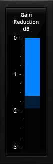 | 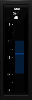 | The GAIN CONTROL METER supports two distinct modes. Click the meter title to switch between both modes: · Gain Reduction Shows the amount of gain reduction (in dB) taking place in the gain cell. Note that this does not reflect the effect of DRY MIX and FDR. · Total Gain Shows the total amount of gain applied to the signal. Note that this mode also does not reflect the effect of FDR (doing so would ask for an unreasonable amount of computing power). The scale automatically grows with the amount of gain reduction. Rolling over the display makes two “+” and “-” buttons appear (when possible) which allow increasing or decreasing the range as needed. A right or left click will also increase or decrease gain reduction meter range respectively. |
Toolbar
Undo/Redo
| Use the undo/redo buttons to navigate to previous control states. The exact event is shown in a tool-tip. Note that certain controls are not tracked by this function (e.g. “Bypass”). |
Preset Management
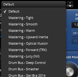 | The preset drop-down list offers quick access to factory settings and user presets. Alternatively, the up/down buttons allow you to cycle through the presets. |
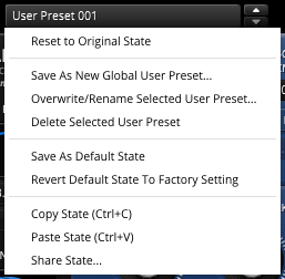 | Advanced preset management options can be accessed from the preset bar’s context menu (right-click): Reset to Original state resets the preset to its original state. Save As New Global User preset opens a dialog used to create User Presets. These presets persist across sessions and DAWs (presets are saved on your machine). The total amount of user presets is limited to ten. Save As Default State replaces the plugins’ default preset with the current parameter state. Revert Default State To Factory Setting deletes an overwritten default state. See section“Context Menu”below for details about the Copy/Paste/Share State options. |
A/B Control
| A/B allows comparing between two alternative control settings. A>B or B<A copies one state to the other. |
Process-Quality
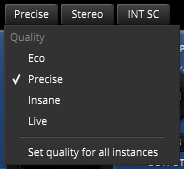 | Kotelnikov GE offers four different quality modes: · Eco: Economic mode, with an internal bandwidth ~100kHz · Precise: Default quality, with an internal bandwidth ~200kHz · Insane: Very high quality, with an internal bandwidth ~400kHz · Live: Low latency mode. Set quality for all instances sets the currently selected quality mode to all instances of the plugin. Please note that this feature has been intentionally designed to be non-creative. With the exception of the “live” option, the different quality modes purely result in different inter-sample accuracy and aliasing byproduct amounts (artifacts). Since the “live” option has to compromise certain aspects for low latency, it can’t be directly compared to the other modes. The compressor for all modes is bit transparent at 0 dB gain reduction. |
Process-Target
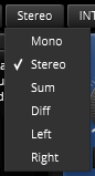 | The audio input can be processed in various channel modes: · Mono sums any input into mono. This is dependent from the plugin host’s channel configuration. · Stereo enables conventional L/R processing. · Sum and Diff represents either “Mid” or “Side” processing accordingly. This processing is exclusive as only the selected target is processed while the other is untouched. Left and Right allow for the left or right channels to be processed exclusively. |
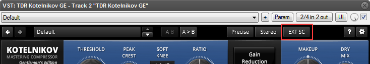
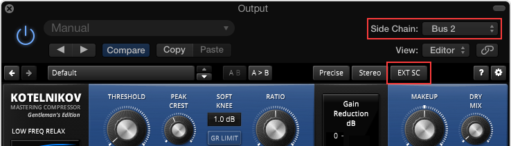
Sidechain Input
 | The sidechain-input dropdown allows using an external signal to drive the sidechain. – INT SC: Internal sidechain input. Uses the input signal to drive the dynamics processor. – EXT SC: External sidechain input. Uses an external signal to drive the dynamics processor. Note: The sidechaining abilities vary greatly across plugin formats and plugin hosts. |
VST 2 / REAPER
- In REAPER, send any “key” signal to the source track’s channel 3 and 4.
- Select “EXT SC” in Kotelnikov GE’s toolbar.
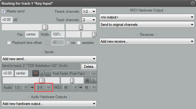
Note: In order to work, plugin host must support multi-input plugins. Sadly, only few s support multiple plugin inputs. Reaper is probably the most popular example.
AU / Logic
- In Logic’s plugin window, assign a bus to operate as a sidechain signal.
- Select “EXT SC” in Kotelnikov GE’s toolbar.
AAX / Pro Tools
- In Pro Tools’ plugin window, assign a bus to operate as a sidechain signal.
- Select “EXT SC” in Kotelnikov GE’s toolbar.
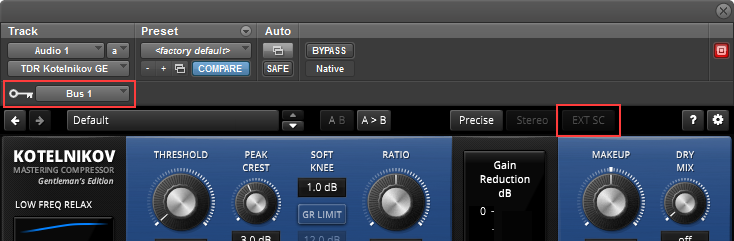
Note: AAX sidechains are always mono.
Help
| The dynamic help mode offers detailed information about the various elements of the user-interface. Click “?” to activate the online help and move the mouse-cursor over the control of interest. A small info bubble will appear. Another left- click closes the help mode. |
Settings
| The settings button opens a dialog which gives control over additional plugin options. |
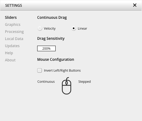
Slider allows for changing the behavior of knobs and control points in response to the mouse. Under Continuous Drag,knob and controller movement relies on mouse speed when Velocity is enabled. When Linear is enabled, knob and controller movement is proportional to mouse movement. Drag Sensitivity sets the linear sensitivity of the knob and controller movement further.
Plug-in controls, knobs, and control points can be adjusted using Left-click & drag (Continuous) and Right-click & drag (Stepped) by default. Mouse Configuration swaps the Continuous and Stepped behaviors between the left and right mouse buttons when selecting Invert Left/Right Buttons. Note that the default stepped values can be customized via the product configuration file. See “Local data” below for instructions on how to access this file.
Graphics allows for changing the interface size to a fixed percentage value between 100%, 125% and 150%.
Processing shows the plug-in latency and sample rate details. Highest quality rendering enables the option to always render at the highest Processing Quality, no matter what type is enabled in the Toolbar. See the “Processing Quality” subchapter for more details on these modes.
Registration offers access to offline and online product registration options. See the “Product Registration” chapter for more information.
Local Data allows for exporting and importing user preferences, presets, and keys, to and from other systems. Local data can also be deleted for all Tokyo Dawn Labs plug-ins using the Trash Can button.
In addition, the Folder button opens the Tokyo Dawn Labs local data folder containing all configuration files and keys. Note that these operations affect all TDR plug-ins, and not just TDR Limiter 6 GE.
Updates allows to Check for updates and to Download latest version. Automatic Lookups can be enabled to Check for updates (once per day).
Help contains Documentation and Support links.
About shows the version number, build date, format, credits, and other information.
Context Menu
Standard Context Menu
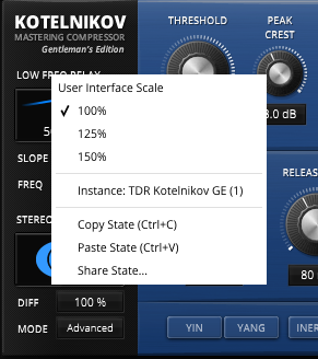 | Additional options can be accessed using the standard context menu. This can be opened by right-clicking on a blank area anywhere in the UI. A click outside of the menu closes it. User Interface Scale sets the on-screen interface size to a fixed percentage value of 100%, 125%, or 150%. Instance allows for renaming the specific plug-in instance. Copy State (Ctrl+C) and Paste State (Ctrl+V) allows copying control states (i.e. “presets”) across plugin instances and plugin hosts. Share State opens a dialog with additional preset sharing options via e-mail or internet forums. |
Appendix A: Getting started with Kotelnikov GE
While all these advanced concepts of Kotelnikov GE might appear a bit intimidating at first, special care has been taken to make it as easy to use as classic compressor – you’ll benefit from the sonic goodies right away, and can learn how to fine tune details later on, while already using Kotelnikov GE in your mixes.
Please load the default preset. We’ll focus on these three controls for now:
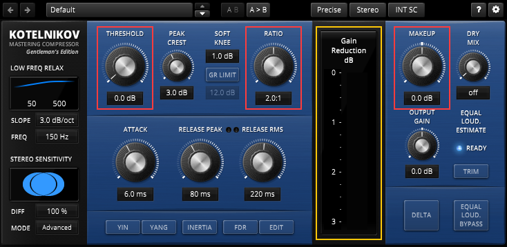
Play a simple signal, say an acoustic drum loop. Now move the THRESHOLD knob clockwise until the GAIN REDUCTION METER flashes up during loud passages. Notice how the signal gets more dense, stronger and punchy without actually getting louder. In simple terms, you can think of THRESHOLD as the level at which of compression starts working.
RATIO controls the strength of compression – a RATIO of 1.0:1 means there is no compression at all. The range between 1.5:1 and 3.0:1 is a good universal starting point.
The GAIN REDUCTION METER will give you visual feedback of the processing, and you can use the MAKEUP knob to recover the level lost during the compression process. After compensating the level via MAKEUP, you should be hearing a satisfying increase in density.
Next we’ll look at the ATTACK parameter – it controls how fast the compressor reacts to content surpassing the THRESHOLD. Short attack times mean that compressor will respond very quickly, which in turn help to tame fast events such as drums, percussion and similar. This however is not always beneficial. Longer attack times on the other hand tend to accentuate the attack phase of your signal, often adding a sweet “snappy” character to the original signal.
The release knobs work similar way to other compressors at first glance, the main difference being that Kotelnikov GE offers separate control over fast, peaky effects (often described as transients) and the average RMS “body” of the signal.
Now try Kotelnikov GE on various signals, channels as well as groups or the stereo bus, and get familiar with these 6 central controls highlighted in the image below.
Use your ears for now, and make sure to read up the detailed explanation of Kotelnikov GE’s unique timing technology – fascinating, and an amazingly powerful dynamics tool once you get a handle on the “expert parameters”.
To wrap things up, here’s a short glimpse at the remaining, more advanced features, just so you know where to look in case you need deeper control over certain aspects – please refer to the related manual sections for specifics!

This panel on the left gives you control over what part of your signal Kotelnikov GE listens to the most, helping you avoid common problems related to compression. The top section called LOW FREQUENCY RELAX basically tells Kotelnikov GE to ignore low frequencies to a certain degree when adjusting its compression – you don’t want the big, bad kick to duck that fragile little flute.
Likewise, the bottom section named STEREO SENSITITVITY helps you focus Kotelnikov GE’s attention on certain parts of the stereo panorama. Setting DIFF to 0% has the tendency to widen stereo content during compression. The deeper the gain reduction, the wider the sound becomes.
Important: These two specialized sidechain pre-processors do not change your signal directly; they only fine tune the compression character.
PEAK CREST adjusts the relationship between peak- and RMS (average) compression, favoring one or the other. This parameter allows manipulating the compression behavior in a dramatic manner.
A SOFT KNEE of zero means the compression kicks in immediately once a signal passes the threshold like flicking a switch, as opposed to a higher value, which gives you gradual onset of compression.
The right hand section offers various means of level compensation, as well as monitoring helpers such as the BYPASS switch and the (purely informative) DELTA function.
Last but certainly not least, the FDR section is worth some attention. This is a totally unique way of getting different ratios depending on the signal’s frequency.
The mysterious Yin and Yang buttons add subtle compression dependent saturation to low- and high frequencies respectively.
That leaves the top bar, a common feature in all TDR plugins since Slick EQ – here’s where you find the convenience functions to make your life easier, like AB comparison, undo and preset management.
It is worth noting that you can save chose different processing modes for Kotelnikov GE. The default mode “Stereo” works like any other stereo processor. However, you can force mono processing at this point (“Mono”) or even process either the Stereo Sum (representing “Mid” in Mid/Side microphone array) or the Stereo Difference (equivalent to “Side” in Mid/Side microphone array).
Please refer to the main section of the manual for precise, in-depth explanations of all the innovative features above. Take your time, have fun exploring this mighty tool and know that the advanced parameters are preset to sensible values by default and are simply waiting for those special situations when all you need is a little “more”.
Appendix B: Vladimir Aleksandrovich Kotelnikov
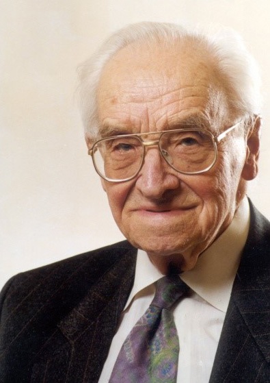
Vladimir Aleksandrovich Kotelnikov (Russian Владимир Александрович Котельников, scientific transliteration Vladimir Alexandrovič Kotelnikov, 6 September 1908 in Kazan – 11 February 2005 in Moscow) was an information theory and radar astronomy pioneer from the Soviet Union. He was elected a member of the Russian Academy of Science, in the Department of Technical Science (radio technology) in 1953. From 30 July 1973 to 25 March 1980 Kotelnikov served as Chairman of the RSFSR Supreme Soviet.
He is mostly known for having discovered the sampling theorem in 1933, independently of others (e.g. Edmund Whittaker, Harry Nyquist, Claude Shannon). This result of Fourier Analysis was known in harmonic analysis since the end of the 19th century and circulated in the 1920s and 1930s in the engineering community. He was the first to write down a precise statement of this theorem in relation to signal transmission. He was also a pioneer in the use of signal theory in modulation and communications.
He is also a creator of the theory of optimum noise immunity. He obtained several scientific prizes for his work in radio astronomy and signal theory. In 1961, he oversaw one of the first efforts to probe the planet Venus with radar. In June 1962 he led the first probe of the planet Mercury with radar.
Kotelnikov was also involved in cryptography, proving the absolute security of the one-time pad; his results were delivered in 1941, the time of Nazi Germany’s invasion of the Soviet Union, in a report that apparently remains classified to today. In this, as with the above-mentioned sampling theorem, he and Claude Shannon in the US reached the same conclusions independently of each other. For his achievements Kotelnikov was awarded the IEEE 2000 Gold Medal of Alexander Graham Bell and the honorable IEEE Third Millennium Medal. Prof. Bruce Eisenstein, the President of the IEEE, described Kotelnikov as ”The outstanding hero of the present. His merits are recognized all over the world. In front of us is the giant of radio engineering thought, who has made the most significant contribution to media communication development” – [Extract from Wikipedia http://en.wikipedia.org/wiki/Vladimir_Kotelnikov]
A note from the developers: The decision to call this compressor “Kotelnikov” is primarily a tribute to a person deeply involved in the most important technological developments of the 21st century. It also nicely reflects the “no-nonsense” scientific claim of this product as well as its deep respect for sampling theorem. Last but not least, we hope the name is as memorable as we’re supposing.